Yaskawa RP-Y01-2ZI pendant with 7i73
- COFHAL
- Offline
- Platinum Member
-

Less
More
- Posts: 457
- Thank you received: 62
24 Nov 2023 02:23 #286380
by COFHAL
Replied by COFHAL on topic Yaskawa RP-Y01-2ZI pendant with 7i73
When adding setp nvdispmode 1064 the error appears: pin setp nvdispmode does not exist. I think we must add a component that generates this pin.
Please Log in or Create an account to join the conversation.
- PCW
-

- Offline
- Moderator
-

Less
More
- Posts: 17989
- Thank you received: 5281
24 Nov 2023 02:46 #286381
by PCW
Replied by PCW on topic Yaskawa RP-Y01-2ZI pendant with 7i73
You need the full name, for example on a 7I96S with a 7I73, it would be
setp hm2_7i96s.0.7i73.0.0.nvdispmode 1064
Note! You should do this with halshow or halcmd, not in a hal file:
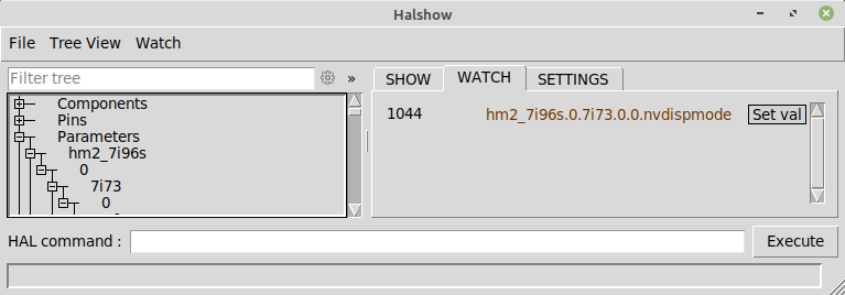
Also note that NV parameters do not take effect until you power
cycle the sserial device. NV parameters should be treated with caution
since some can brick the card
setp hm2_7i96s.0.7i73.0.0.nvdispmode 1064
Note! You should do this with halshow or halcmd, not in a hal file:
Also note that NV parameters do not take effect until you power
cycle the sserial device. NV parameters should be treated with caution
since some can brick the card
Attachments:
Please Log in or Create an account to join the conversation.
- COFHAL
- Offline
- Platinum Member
-
Less
More
- Posts: 457
- Thank you received: 62
24 Nov 2023 16:43 #286413
by COFHAL
Replied by COFHAL on topic Yaskawa RP-Y01-2ZI pendant with 7i73
Thank you for your support. The 4 x 40 LCD display works well, I recognized it without problem.
Please Log in or Create an account to join the conversation.
- Malcolm
- Offline
- New Member
-

Less
More
- Posts: 4
- Thank you received: 0
28 Jan 2024 23:43 #291852
by Malcolm
Replied by Malcolm on topic Yaskawa RP-Y01-2ZI pendant with 7i73
Hi all,
I just pulled the trigger on one of the Yaskawa pendants that radar_macgyver posted about, as well as a 7i73.
Big thanks to radar_macgyver for the work in the board design and revision. I'm in the process of figuring out KiCad and some a couple of the online pcb manufacturers to get a board made.
I saw that the topic here hasn't seen a lot of activity recently, and was hoping to see where folks were at with it, and maybe pointers on sourcing the pcb, or purchasing a spare from someone who had extras made.
@MikeRomill: If you're seeing this did you ever get this set up?
@radar_macgyver: If you're seeing this, did you ever do anything else with the design beyond V2? Once I get things going and have a better handle on KiCad I'd love to take a stab at bringing up the led functionality and addressing some of the remaining bugs.
Please Log in or Create an account to join the conversation.
- MikeRomill
- Offline
- New Member
-
Less
More
- Posts: 3
- Thank you received: 0
29 Jan 2024 01:10 #291857
by MikeRomill
Replied by MikeRomill on topic Yaskawa RP-Y01-2ZI pendant with 7i73
I haven’t been able to work on that project yet; it’s been a busy year for me, but still on my list of things to finish.
Please Log in or Create an account to join the conversation.
- Malcolm
- Offline
- New Member
-
Less
More
- Posts: 4
- Thank you received: 0
01 Feb 2024 19:31 #292157
by Malcolm
Replied by Malcolm on topic Yaskawa RP-Y01-2ZI pendant with 7i73
No worries, Mike. I certainly know how life can get in the way of fun little side projects.
I just did a minimum order on jlcpcb of 5 boards, with 2 of them mostly assembled.
This is my first time using an online pcb fab, so it's been a bit of an adventure. Hopefully I did everything correctly and I can get the pendant up and running quickly.
Once I've got them in hand and can start playing around with them I'll report back here.
Please Log in or Create an account to join the conversation.
- Malcolm
- Offline
- New Member
-
Less
More
- Posts: 4
- Thank you received: 0
13 Feb 2024 03:00 #293188
by Malcolm
Replied by Malcolm on topic Yaskawa RP-Y01-2ZI pendant with 7i73
Well, my mostly assembled boards came on Friday and I finished assembling and integrating over the weekend. It was my first time ordering a pcb online, and I'm blown away at just how quickly and cheaply you can get boards made overseas. 5 PCBs, 2 mostly assembled, and all in hand 8 days after ordering for 50 bucks. Wow!
I had just the top sides of the boards assembled due to price and component availability. Soldering went pretty smoothly.
Took a little while to get the config files properly adjusted for my setup. The 7i73 seems to be on smart serial port 1, not 0.
I haven't looked into it further, but my keyboard matrix rows and columns were reversed from the original config.
And I'm not sure if it's a bug, but my panelui.ini wasn't being picked up until I renamed it to "_panelui.ini" with the leading underscore. My python is pretty rusty but a quick glance over the source changes on github didn't reveal any obvious changes that would cause that behavior.
All in all, the device is working exactly as radar_macgyver described, and I couldn't be happier.
Radar if you find your way back to this forum, thank you so much for all the effort and sharing it all with us! I'd love to learn a little more about how the LED circuitry and work on a board revision that could drive them, possibly with a set of mosfets and bringing in extra 24v.
The cable that came with the pendant has sufficient conductors in it to land 8 on the 7i73, plus 2 for 24v/ground, plus 2 for the e-stop if one wanted to go that route. There are 3 thin conductors in the cable that are unused and cut back, so stripping the cable further back and crimping/terminating would be required.
Mike- as I mentioned I got 2 boards assembled. If you're interested in either a populated or unpopulated board to get yours moving along, I'd be happy to get one to you for what it cost me.
I'm uploading a photo of the new board side by side with the original pendant board it replaces in case any one is curious. Otherwise there's not much more to add photos-wise that radar didn't already include.
If I make any improvements to the configs or board design in the future, I'll be sure to post them here.
Please Log in or Create an account to join the conversation.
- radar_macgyver
- Offline
- New Member
-
Less
More
- Posts: 10
- Thank you received: 8
14 Feb 2024 08:46 #293307
by radar_macgyver
Replied by radar_macgyver on topic Yaskawa RP-Y01-2ZI pendant with 7i73
Hello Malcom,
Thanks for tracking me down on the eevblog forum") Sorry I can't seem to get notifications working on this forum.
Sorry I can't seem to get notifications working on this forum.
The LEDs on the board are driven as a matrix, with the rows separate, while the columns are shared with the keypad. You can verify that the LEDs operate by applying a voltage between the KP_COLx pins and the LED_ROWx pins. My recollection was the LED_ROWx pins must be grounded, and the COLx pins connected to VCC, but in the switch from PCB rev 1 to rev 2, I could have flipped these around. The keypad/LED board does contain FETs that switch the +24V to the columns of the LEDs, so one needs to provide a supply voltage to the LED board (pins 1 through 6 and pins 45 through 50) before testing. Wish I kept my notes from when I reverse-engineered the board...
You'll note that the LED_ROWx pins are connected to the KP_ROWx pins through a resistor network, the intent being that if the 7i73 scans the keyboard rows by pulling each one low, and also drives the COLx pins simultaneously, the LED will light up. Admittedly, this is quite a kludge, a much better way would be to maybe use a pair of registers to store the ROWx output bits from the 7i73 (gated by, say, the OUT1 and OUT2 pins) and drive the LED_ROWx pins with one register and the KP_ROWx pins with the other. The normal keyboard scanning routine will continue to drive the keyboard and LED's column inputs. By switching on alternate cycles between OUT1 and OUT2, the keyboard and LED matrices are scanned.
For either method to work, the 7i73 must have firmware loaded so that it is aware the I/Os are used as part of a scanned matrix. This would need the help of PCW or someone else who has the firmware for the micro on the 7i73, plus exposing the resulting 6x8 inputs to LinuxCNC.
You shouldn't need +24V, you could instead replace the SMD 2.2k dropper resistors on the Yaskawa board with lower resistance versions, and tie together the +24V and +5V rails (resistor 'R4' on the board).
Thanks for tracking me down on the eevblog forum
Sorry I can't seem to get notifications working on this forum.The LEDs on the board are driven as a matrix, with the rows separate, while the columns are shared with the keypad. You can verify that the LEDs operate by applying a voltage between the KP_COLx pins and the LED_ROWx pins. My recollection was the LED_ROWx pins must be grounded, and the COLx pins connected to VCC, but in the switch from PCB rev 1 to rev 2, I could have flipped these around. The keypad/LED board does contain FETs that switch the +24V to the columns of the LEDs, so one needs to provide a supply voltage to the LED board (pins 1 through 6 and pins 45 through 50) before testing. Wish I kept my notes from when I reverse-engineered the board...
You'll note that the LED_ROWx pins are connected to the KP_ROWx pins through a resistor network, the intent being that if the 7i73 scans the keyboard rows by pulling each one low, and also drives the COLx pins simultaneously, the LED will light up. Admittedly, this is quite a kludge, a much better way would be to maybe use a pair of registers to store the ROWx output bits from the 7i73 (gated by, say, the OUT1 and OUT2 pins) and drive the LED_ROWx pins with one register and the KP_ROWx pins with the other. The normal keyboard scanning routine will continue to drive the keyboard and LED's column inputs. By switching on alternate cycles between OUT1 and OUT2, the keyboard and LED matrices are scanned.
For either method to work, the 7i73 must have firmware loaded so that it is aware the I/Os are used as part of a scanned matrix. This would need the help of PCW or someone else who has the firmware for the micro on the 7i73, plus exposing the resulting 6x8 inputs to LinuxCNC.
You shouldn't need +24V, you could instead replace the SMD 2.2k dropper resistors on the Yaskawa board with lower resistance versions, and tie together the +24V and +5V rails (resistor 'R4' on the board).
The following user(s) said Thank You: Malcolm
Please Log in or Create an account to join the conversation.
- radar_macgyver
- Offline
- New Member
-
Less
More
- Posts: 10
- Thank you received: 8
14 Feb 2024 08:59 #293308
by radar_macgyver
Replied by radar_macgyver on topic Yaskawa RP-Y01-2ZI pendant with 7i73
Another way to drive the LEDs could be using the ROW6/ROW7 pins. Since the keypad is really a 6x8 matrix and ROW6/7 are not used by the keypad, these could be used to drive a subset of the LEDs by connecting them to LED_ROWx.
Please Log in or Create an account to join the conversation.
- Malcolm
- Offline
- New Member
-
Less
More
- Posts: 4
- Thank you received: 0
15 Feb 2024 23:21 #293463
by Malcolm
Replied by Malcolm on topic Yaskawa RP-Y01-2ZI pendant with 7i73
Wow, thanks for the thorough write-up!
Having the "dual-use" keyboard matrix pins makes it a bit trickier for me to wrap my brain around the intended functionality, but I generally understand what you mean, being familiar enough with standard keyboard matrices.
I jumped the gun a little bit when my new boards arrived and never soldered in resistor arrays to the back side for the LEDs. Experimentation will probably have to wait until I can source a few and solder them into the second board, since they're a little too close to the 2mm pitch pin headers for my shaky hands to be able to solder in.
My personal preference would be to leave the original parts as untouched as possible, and run a dedicated 24v line, especially if it means leaving the existing resistors alone. In the end I'm not committed to it though.
I was considering attempting to reuse the original cable, since while it appears to lack twisted pairs, it does have robust shielding, 8 total smaller gage wires (just checked and they will fit under an RJ45 terminal), plus 2 heavier pairs that could be used for dedicated 24V+ground and estop circuit. Just have to cut the shielding back a bit to get to the 3 unused conductors, and re-terminate the bulkhead connector. Looking into a compatible fitting for my controls cabinet, think I found one on Misumi.
As to the bigger picture in driving the LEDs, do I understand correctly that the 7i73 simply isn't up to the task given the current firmware limitations?
Side note, as far as I can tell I'm subscribed to the topic here but I'm not seeing email notifications for new replies. So it's not just you!
Please Log in or Create an account to join the conversation.
Time to create page: 0.378 seconds