Universal Control panel build
- blazini36
- Offline
- Platinum Member
-

- Posts: 972
- Thank you received: 167
The gist is I wanted to make a "universal" type of LinuxCNC control box. For one so I can have a standard thing I can grab for any future machines I make as I tend to make weirdo stuff sometimes and don't want to be too bothered with this portion of it. Another idea is that I can offer them for sale to anyone who wants something like this and doesn't want to bother with it themselves. The ladder isn't a super likely scenario as these are #NotCheap to make, but since I already put in (most of) the effort I'll have most of the stuff around if anyone wants one.
Gotta thank spumco since he put in quite a bit of time helping me out with plasma cutting a whole bunch of metal. He also sorta pushed me towards the whole "adjustable keyboard" thing though he wasn't really fond of how I did it.
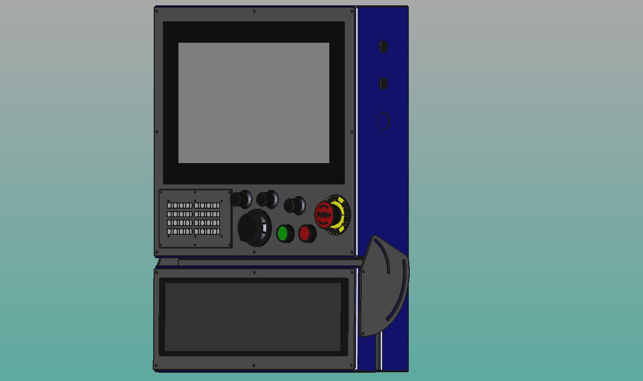
This was the actual CAD design and I was at the very least able to build it as I designed it without too much issue.
The hinge design I wasn't too sure about but it worked great. It was suggested that I hide the hinges inside the enclosure but I can say for certain that would be much more difficult to pull off.
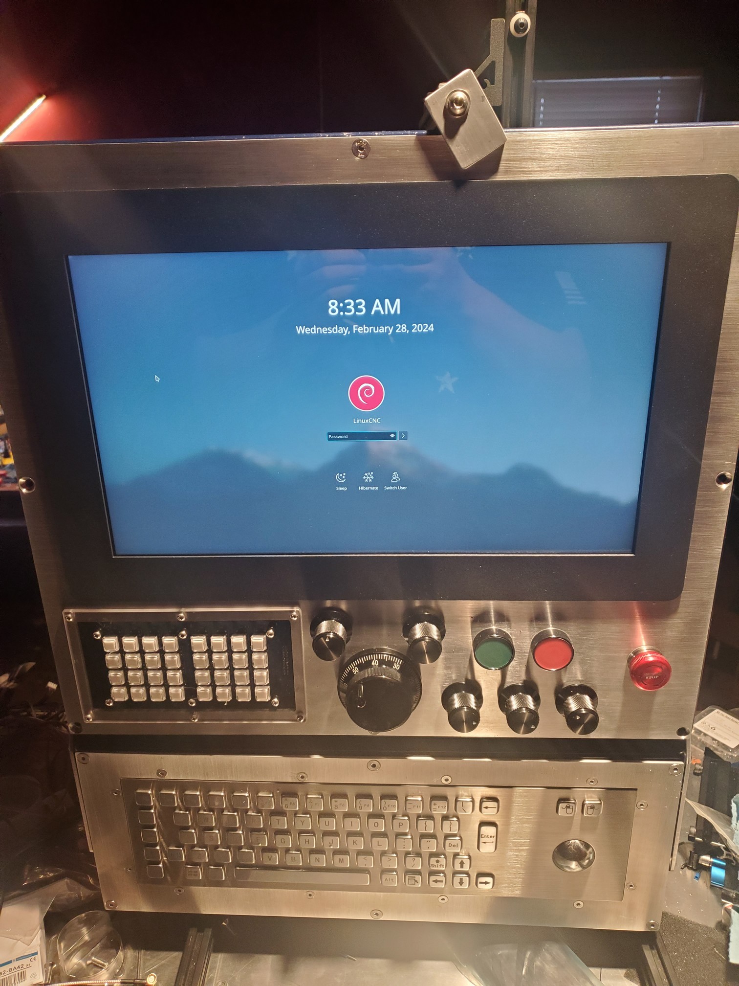
I'm currently building the "prototype" as in I gave it a shitty spray paint job and the unfinished aluminum is getting all scuffed up. This one will get stripped down and powdercoated with the other few I had cut after I finish those. I modified a little stand I made for something else so I could work on this on the table:
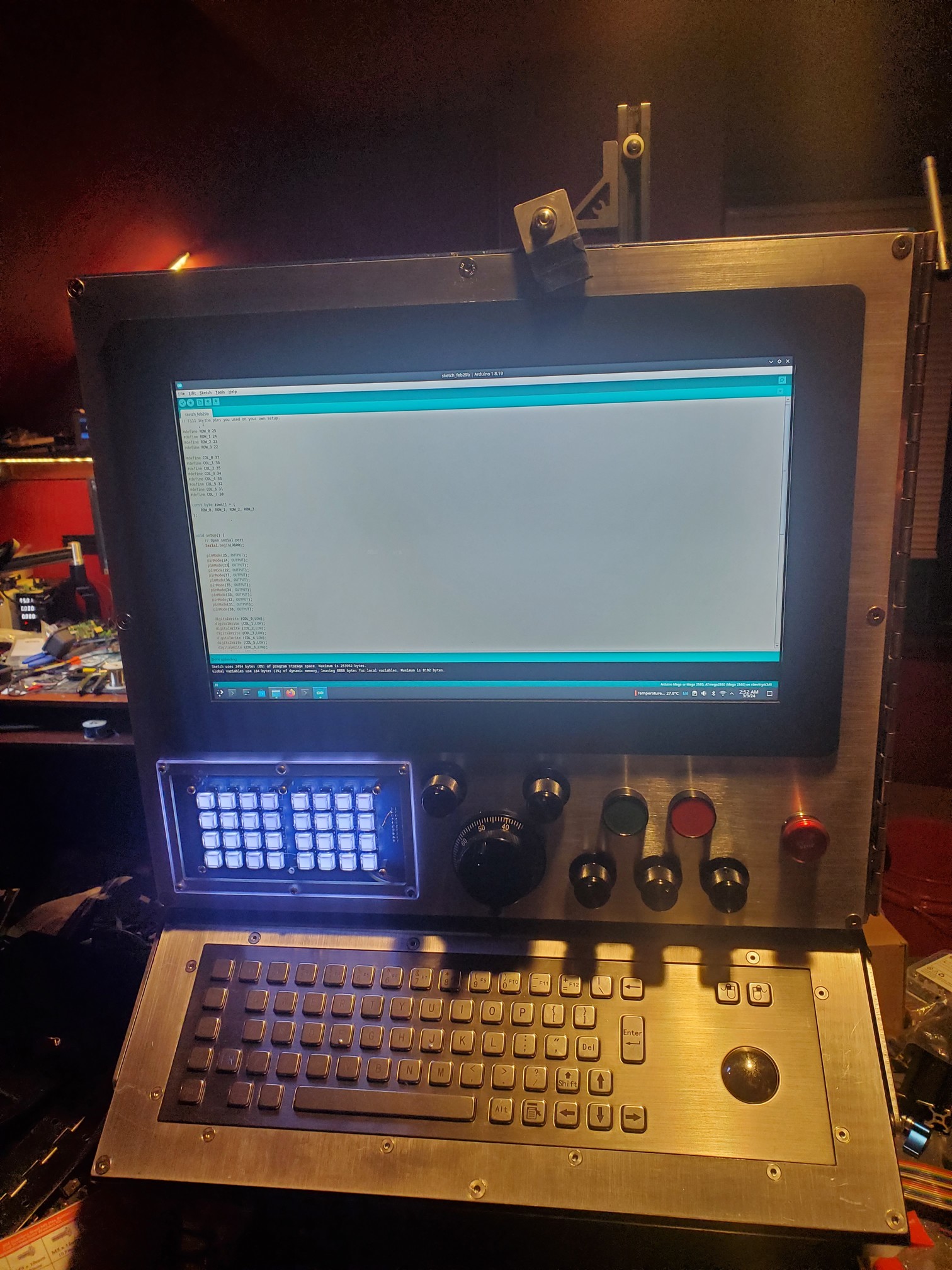
In the second picture (in addition to more shit all over the table), I added a piano hinge to the main panel as it was getting obvious that it was a bit too difficult to do maintenance on having to remove the panel, disconnect it, and stick it somewhere while trying to not damage the too expensive touchscreen. That hinge will be powdercoated with the enclosure so it doesn't look so tacky. The keyboard and trackball are working out really nicely.
The Matrix key panel that's all lit up on the left likely won't be the final iteration, all those buttons cost too much to make it feasible. The clear acrylic mounting panel is also just a test piece. The idea there was a clear label could be stuck under the clear keycaps and the buttons could be HAL'd to do whatever since it wasn't set in stone. I'm currently looking at doing something with conductive rubber membranes for that panel. I never really liked those little dome switch keypads and they likely cost too much to run in such small numbers.
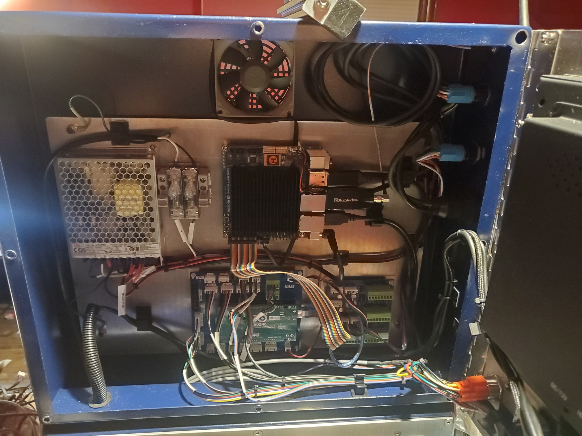
In addition to the matrix keypad I made a couple other custom PCBs for this. This is meant to use "Arduino-connector" with an Arduino Mega as it's all readily available and control panels don't exactly have to be real-time. I'm currently having a bunch of issues with Arduino-Connector, hopefully the author will be able to help, otherwise I've reached out to a friend who's probably tired of me begging for code by now.
Anyway, the larger PCB is an Arduino BOB. Doesn't do much other than break out all of the pins into easy to wire connectors for each peripheral. The whole enclosure only has the one 12v power supply so the BOB also has a 5v switching regulator (under the Arduino) that provides 5v to everything as the regulator on the Arduino and the mini PC would be spread a little too thin. The BOB also takes an enable signal from the PC to turn it on so the IO isn't powered if the PC is turned off.
The smaller PCB to the right of the BOB is an IO expansion for the Odroid H3 MiniPC. I use Odroid H2/H3s in damn near everything so this PCB has a bit more than necessary for this project but I don't really want to make separate PCBs for everything I do. The H3 Expander takes the IO header on the H3 and breaks it out into 3 extra USB ports, a configurable RS422/RS485 HD/FD real serial port, has a level translated I2C connector for adding something like a 20x4 LCD module or whatever straight to the Odroid. The Arduino BOB also has an external I2C port for whatever it could possibly be worth. The H3 expander also has a built in 16 pin IO expander that gives 16 GPIO straight to the H3. Even though Odroid calls the H3's 24pin header a "GPIO" header, it doesn't actually have any GPIO on it. No use for the IO expander on this project but it's there nonetheless.
The Estop button turned out to be smaller than I imagined it. I have some new typical plastic Estops sitting around but I think I'll keep the aluminum one, doesn't bother me too much that it's a bit small. As most Estops have 2 sets of contacts I run 1 set to the Arduino to alert HAL of the condition but the other contact is meant to be run out of the case to the motion controller box for typical Estop business. Never trust USB or serial for an Estop.
There's quite a bit of unused space in the enclosure but everything I need is in there so I I just stuck everything behind the monitor panel. Theres a pretty reasonable sized pocket behind the keyboard enclosure if I needed to stick more stuff in there. I have to tidy up the wiring a bit but since I need to tear it back apart for powdercoating, it's fine for now.
Attachments:
Please Log in or Create an account to join the conversation.
- tommylight
-

- Away
- Moderator
-

- Posts: 21225
- Thank you received: 7248
How about adding a light pole on top , that semaphore thingy?
Please Log in or Create an account to join the conversation.
- rodw
-

- Offline
- Platinum Member
-

- Posts: 11666
- Thank you received: 3930
Please Log in or Create an account to join the conversation.
- blazini36
- Offline
- Platinum Member
-

- Posts: 972
- Thank you received: 167
Could be added, I don't plan on using one so I didn't even think about it.Looks awesome, thank you.
How about adding a light pole on top , that semaphore thingy?
The ones I've seen are all 12/24v like this one on Amazon
The BOB doesn't have any 12v IO, just the typical 5v and those seem like they'd use a bit too much current per output anyway, not really sure. If I do another version of the BOB I could add some 12v, higher current outputs. Besides that some little 4 channel mosfet or opto board off Amazon could handle it
Please Log in or Create an account to join the conversation.
- blazini36
- Offline
- Platinum Member
-

- Posts: 972
- Thank you received: 167
That turned out really nice. I like your BOB for the H3. I did something similar which was also a hat for a 7i73 but then I ended up using ethercat!
Ethercat for a control panel?
I thought about using a 7i73 but there's 2 issues. For one it doesn't have enough current per output to really drive LEDs unless they're tiny and the 2nd problem is it requires a host card which generally isn't a problem for most LinuxCNC users other than the extra serial cable that would have to be run back to the control panel from the box housing the host card. I wanted to keep this "Mach compatible" even though I've never used Mach myself and don't plan on messing with it. Just didn't want to make something that was absolutely limited to LinuxCNC.
I've got a couple of smaller PCBs that plug straight into the H3 header, one is isolated UART+power button break out. The other is Isolated RS232+power button. I wanted to break out the extra USB ports as I plan to wire the touchscreen and keyboard to the H3 expander board's USB ports, I've never really liked normal USB connectors inside of cabinets. The Arduino is already plugged into the expander.
Please Log in or Create an account to join the conversation.
- rodw
-

- Offline
- Platinum Member
-

- Posts: 11666
- Thank you received: 3930
Yes, we did locate complete ethercat control panels. eg. Something like this
Ethercat for a control panel?
panelmategroup.en.made-in-china.com/prod...l-Panel-Codesys.html
Please Log in or Create an account to join the conversation.
- rodw
-

- Offline
- Platinum Member
-

- Posts: 11666
- Thank you received: 3930
Please Log in or Create an account to join the conversation.
- blazini36
- Offline
- Platinum Member
-

- Posts: 972
- Thank you received: 167
Lol yeah I already said thatAlso, 5 volt deos not need to be an issue, Just use opto couplers or level shifter on one of your boards to add a 24 volt logic side.
If I do another version of the BOB I could add some 12v, higher current outputs. Besides that some little 4 channel mosfet or opto board off Amazon could handle it
Please Log in or Create an account to join the conversation.
- blazini36
- Offline
- Platinum Member
-

- Posts: 972
- Thank you received: 167
That's big money. Sounds like you're saying you already have one of these working on your machine?
Ethercat for a control panel?
Yes, we did locate complete ethercat control panels. eg. Something like this
panelmategroup.en.made-in-china.com/prod...l-Panel-Codesys.html
Please Log in or Create an account to join the conversation.
- rodw
-

- Offline
- Platinum Member
-

- Posts: 11666
- Thank you received: 3930
I went the minimalist HMI route with a an estop and 3 buttons
QT_dragon does the rest.
Going the Ethercat route is not necessarilly cheap regardless of what you do..
Please Log in or Create an account to join the conversation.


