retrofit Bridgeport Prototrak Plus
23 Jun 2016 13:52 #76494
by new2linux
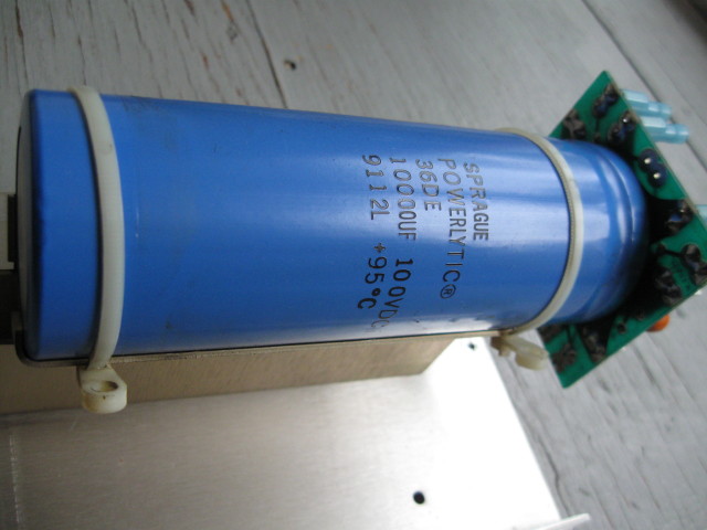
This is the back of the PCB, there is just the big cap on this side.

There is a bit more contrast maybe in this pic to see the PCB
Replied by new2linux on topic retrofit Bridgeport Prototrak Plus
This is the back of the PCB, there is just the big cap on this side.
There is a bit more contrast maybe in this pic to see the PCB
Please Log in or Create an account to join the conversation.
23 Jun 2016 16:24 - 24 Jun 2016 11:53 #76504
by new2linux
Replied by new2linux on topic retrofit Bridgeport Prototrak Plus
Muzzer, You asked this very specific question, and only after taking it apart is it possible to see the circuit board path it has the one from the far side of cap , and one on the cap side.
The plus side of the blue cap goes to the top of R1 and to the top of R2 and to the + side of C2 tatalum cap.
Bottom of R1; C1 and C2 are connected to top copper PCB, the side w/o big cap.
Bottom of R2 looks to go to bottom copper PCB, cap side .
I will look closer or make best sketch if required to clarify or document.
Muzzer's comment from earlier thread "Are there any other components on the other side of the board? Something is limiting the voltage on the tantalum cap to 5V, such as a zener diode. If you trace the tracks from the +ve of the 330uF cap, does it connect through a resistor to the tatalum cap?"
Edit: Best description of resistors: measured with ohm meter
(zeroed out prior to measuring & lifted one end of resistor) meter was in Rx100
scale, and it read half scale, is the 9039F is written on it; measuring R x 100 (scale) it reads 1/3 scale on the one marked 9041F along
with W80S; 2001 and FRJ (is written on both); they measure .435 long x .115 dia.
How to tell if resistor is smoked? It appears to read OHMS in a close range. I need to get order together, and from Andy's comment, I would think that maybe I should buy some stock in a company like Mouser or buy replacement components by the gross count, I plan to replace the resistors as a minimum, if there is a concern other components have been damaged outside the area I have been looking at can we talk about that.
Edit: Mouser will need the resistance, power rating, and tolerance.
many thanks!
Last edit: 24 Jun 2016 11:53 by new2linux. Reason: update
Please Log in or Create an account to join the conversation.
24 Jun 2016 18:09 - 24 Jun 2016 19:09 #76586
by Muzzer
Replied by Muzzer on topic retrofit Bridgeport Prototrak Plus
Incidentally, the large electrolytic shows a date code of 9112 ie week 12 of 1991. That looks consistent with the general appearance of these parts.
Looks as if these resistors were manufactured by Dale (now part of Vishay). That sounds about right because Dale pretty much only maake resistors. The part number W80S2001FRJ comes up as obsolete stock with a few suppliers specialising in that line of work eg Greenlight . Whether or not they genuinely have any in stock is another matter but it's hard to be certain what value they actually are. Nothing magical about them - if you can find what value they are you can replace them with something similar. The 2001 is almost certainly the value (probably 2k) and the W80S is probably the family it comes from and possibly indicates the power rating. The FRJ suffix may refer to the length of the leads and / or whether it was supplied on tape and reel. I can't find any datasheets and Dale seem to have stopped selling these a long time ago.
Trying to fix this without circuit diagrams will be a bit hit and miss, with a high risk of further damage. As Andy says, you'd be advised to get a variable power supply. Have you tried to find schematic circuit diagrams for your system?
Some of the later models have more comprehensive documentation but not surprisingly they don't hand out detailed schematics for the modules themselves. The best I can find is the hand drawn diagram on page 69 of this manual . Might be worth asking around on CNCZone etc to see if anyone has anything better. I see that a replacement Prototrak driver module 15047R-PT is a cool $1142 (exchange) .
Last edit: 24 Jun 2016 19:09 by Muzzer. Reason: Added link to manual
The following user(s) said Thank You: new2linux
Please Log in or Create an account to join the conversation.
24 Jun 2016 19:17 - 24 Jun 2016 19:24 #76591
by new2linux
Replied by new2linux on topic retrofit Bridgeport Prototrak Plus
Muzzer, thanks for your thoughts. The component I have ordered is;
71-CPF2-F-2K
CPF22K0000FKB14
2watts 2Kohms 1%
How do these compare to your requirements.
The variable power supply is to simulate the 5 vdc, is to bench test the assembly. I have a 6.6 v dc power supply that works, will look for 5 v dc if that is the only voltage that will work.
I have went to the manufacture prior to starting this project, they did not even respond. I have the manuals for install on operate but no actual wiring drawing or component documentation. I will draw the diagram if that is what is necessary, of take several pics if that will get the job done. From your comments you believe there are other parts that are bad that have not been discovered.
Edit: The manual you linked to is the one I have. I will ask around, but I am not hopeful.
Thanks for your help!
Last edit: 24 Jun 2016 19:24 by new2linux.
Please Log in or Create an account to join the conversation.

24 Jun 2016 19:25 #76593
by andypugh
The point of the bench power supply is that you can set it to 5V and (say) 100mA and then if there is a fault in the 5V circuits you will see the voltage drop below 5V and the current-limit light come on.
With a non-limited 5V supply you will spot the faulty components by the smoke and sparks from adjacent parts.
Replied by andypugh on topic retrofit Bridgeport Prototrak Plus
The variable power supply is to simulate the 5 vdc, is to bench test the assembly. I have a 6.6 v dc power supply that works, will look for 5 v dc if that is the only voltage that will work.!
The point of the bench power supply is that you can set it to 5V and (say) 100mA and then if there is a fault in the 5V circuits you will see the voltage drop below 5V and the current-limit light come on.
With a non-limited 5V supply you will spot the faulty components by the smoke and sparks from adjacent parts.
The following user(s) said Thank You: new2linux
Please Log in or Create an account to join the conversation.
- Todd Zuercher
-

- Away
- Platinum Member
-

Less
More
- Posts: 4963
- Thank you received: 1369
24 Jun 2016 19:29 #76594
by Todd Zuercher
Replied by Todd Zuercher on topic retrofit Bridgeport Prototrak Plus
I'm not sure we even know for sure what voltages were being used before. When I said 5 and 26v before, I was going by what I could see written on the side of the transformer in the pictures. I could see 0 and 26 clearly, but the other number was always mostly obscured in the photos by wires, and I guessed that it was a 5. Could you confirm the numbers on the transormer, and better yet, measure the actual voltages between 0 and 26, and 0 and the other terminal. Remember those will be AC voltages.
The following user(s) said Thank You: new2linux
Please Log in or Create an account to join the conversation.
24 Jun 2016 19:59 #76596
by Muzzer
Replied by Muzzer on topic retrofit Bridgeport Prototrak Plus
CPF22K0000FKB14 (2k, 2W) sounds about right - assuming we have guessed the value correctly. But is this based on the markings of the surviving resistor or the one that burned out? That resistor would be available in a massive range of values.
Fairly likely that any control circuit from the early 90s would want 5V as that's what micros and logic devices ran on in those days. Just what the current demand would be is another guess...
Fairly likely that any control circuit from the early 90s would want 5V as that's what micros and logic devices ran on in those days. Just what the current demand would be is another guess...
The following user(s) said Thank You: new2linux
Please Log in or Create an account to join the conversation.
24 Jun 2016 21:36 #76605
by new2linux
Replied by new2linux on topic retrofit Bridgeport Prototrak Plus
When I check the voltages between the 0 and 26 meter reads 0.5 volt and immediately drops off; 0 and 52 0.8 or 0.9 volt and immediately drops off. The needle almost looks to go negative, but believe it is the bounce of the needle going below 0 is what I am seeing.
Please Log in or Create an account to join the conversation.
- Todd Zuercher
-
- Away
- Platinum Member
-
Less
More
- Posts: 4963
- Thank you received: 1369
24 Jun 2016 22:20 #76611
by Todd Zuercher
Replied by Todd Zuercher on topic retrofit Bridgeport Prototrak Plus
Are you checking the voltage with the power turned on and your meter set for AC? (you can unhook the wires that went to the amp while testing.)
The following user(s) said Thank You: new2linux
Please Log in or Create an account to join the conversation.
24 Jun 2016 22:52 - 24 Jun 2016 22:55 #76614
by new2linux
Replied by new2linux on topic retrofit Bridgeport Prototrak Plus
It needs time to charge up, but only goes 0.5 v on 0 to 26; and only 1.5 v 0 to 52. It definitely has a negative direction before going positive on meter it seems. How important is computer to be powered up? Small control cables from p/s amp were unhooked this time, I may not of allowed time to get full charge last reading.
Edit: the resisters I have re soldered in place, just to clarify.
Edit: the resisters I have re soldered in place, just to clarify.
Last edit: 24 Jun 2016 22:55 by new2linux. Reason: to clarify
Please Log in or Create an account to join the conversation.
Moderators: piasdom
Time to create page: 0.510 seconds