retrofit Bridgeport Prototrak Plus
- Todd Zuercher
-

- Away
- Platinum Member
-

Less
More
- Posts: 4963
- Thank you received: 1369
24 May 2016 14:22 #75042
by Todd Zuercher
Replied by Todd Zuercher on topic retrofit Bridgeport Prototrak Plus
If you are reusing the breakout board, they are grounded there, connecting them to another place could set up a ground loop and cause some electrical noise. If you are not using the board, then they will need to be grounded somewhere and at the 7i77 would be a good place.
Please Log in or Create an account to join the conversation.
24 May 2016 15:29 #75045
by new2linux
Replied by new2linux on topic retrofit Bridgeport Prototrak Plus
Just to confirm about the shield for the pins in the plug, there are 3 pins that go to ground on the male half of plug, in the mating half of plug it is ok to jumper 2 of the wires coming from the back into one socket with wire going to ground on the base of the card, where the card attaches to cabinet under a screw or is there a specific ground location.

The red plug is just laying there to show the wire positions, for the X (P1-P2) this is the TB5 PIN 3 and 4 locations on the 7i77 and on the Y (P3-P4) this is the TB5 PIN 7 and 8 locations are used.
Referencing the red plug, from an earlier comment that the black jumper pins may be used (as you can see I have a wire coming from each pin that was used in the old controller) as input as well, but what location on the 7i77?
many thanks!
Please Log in or Create an account to join the conversation.
- Todd Zuercher
-
- Away
- Platinum Member
-
Less
More
- Posts: 4963
- Thank you received: 1369
24 May 2016 17:39 #75047
by Todd Zuercher
Yes they can and should be all connected together.
Are you asking where you should connect the wires that were the old jumper?
If so, first you need to figure out what exactly they are and do. When the jumper is disconnected does it in fact disable the amp, or does it do something else?
What kind of voltage did the jumper carry? AC, DC, which wire is +, which is -?
If they are an enable, and they are DC current, less than 100v and 50mA, you could connect the one for the X, positive wire to TB5 pin2 on the 7i77 and the negative wire to TB5 pin1.
Once you have a basic config, set up for Linuxcnc, the first thing you want to do is test the encoders. I'd suggest leaving the amps disconnected at this point. Once you have the encoders working (turning the motor moves the DRO in Linuxcnc). Then you are ready to try the amps. You could enable the amp and apply a small voltage with a battery (think AA or C battery), see if the motor turns. This might give a clue how you should connect the analog wires to the 7i77. Then you are ready to test the amp connected. Be prepared for a runaway (the odds of it happening is at least 50/50).
Once everything is connected you are ready to do a little tuning. Read some of the tutorials about servo tuning.
Replied by Todd Zuercher on topic retrofit Bridgeport Prototrak Plus
Just to confirm about the shield for the pins in the plug, there are 3 pins that go to ground on the male half of plug, in the mating half of plug it is ok to jumper 2 of the wires coming from the back into one socket with wire going to ground on the base of the card, where the card attaches to cabinet under a screw or is there a specific ground location.
Yes they can and should be all connected together.
The red plug is just laying there to show the wire positions, for the X (P1-P2) this is the TB5 PIN 3 and 4 locations on the 7i77 and on the Y (P3-P4) this is the TB5 PIN 7 and 8 locations are used.
Referencing the red plug, from an earlier comment that the black jumper pins may be used (as you can see I have a wire coming from each pin that was used in the old controller) as input as well, but what location on the 7i77?!
Are you asking where you should connect the wires that were the old jumper?
If so, first you need to figure out what exactly they are and do. When the jumper is disconnected does it in fact disable the amp, or does it do something else?
What kind of voltage did the jumper carry? AC, DC, which wire is +, which is -?
If they are an enable, and they are DC current, less than 100v and 50mA, you could connect the one for the X, positive wire to TB5 pin2 on the 7i77 and the negative wire to TB5 pin1.
Once you have a basic config, set up for Linuxcnc, the first thing you want to do is test the encoders. I'd suggest leaving the amps disconnected at this point. Once you have the encoders working (turning the motor moves the DRO in Linuxcnc). Then you are ready to try the amps. You could enable the amp and apply a small voltage with a battery (think AA or C battery), see if the motor turns. This might give a clue how you should connect the analog wires to the 7i77. Then you are ready to test the amp connected. Be prepared for a runaway (the odds of it happening is at least 50/50).
Once everything is connected you are ready to do a little tuning. Read some of the tutorials about servo tuning.
The following user(s) said Thank You: new2linux
Please Log in or Create an account to join the conversation.
25 May 2016 12:53 #75072
by new2linux
Replied by new2linux on topic retrofit Bridgeport Prototrak Plus
Todd, Many thanks for your very helpful comments! By visual and or voltmeter tracing from the pins in question would this provide any hint or suggestion to reduce the number of variables?
If that were to be successful would the unknowns be so that if wired incorrectly it would not do harm to the electronic components?
Are all 4 unknowns, mission critical vs. trial and error? If it were absolutely necessary to have a oscope attached to monitor and gather info would it require the system to be powered up as the old controller configuration, or would it be analyzing the current set of components?
The reason for that question is deciding if the person with the oscope will need to come here or what needs to be taken to him. From earlier I had read that some of these connections have some allowance for safety (against permanent damage) and others do not.
Many Thanks!
Please Log in or Create an account to join the conversation.
- Todd Zuercher
-
- Away
- Platinum Member
-
Less
More
- Posts: 4963
- Thank you received: 1369
25 May 2016 15:36 #75075
by Todd Zuercher
Replied by Todd Zuercher on topic retrofit Bridgeport Prototrak Plus
I don't think you need an O-scope. for the following tests.
1st with the amps powered and connected (working) what is the state of all the LEDs on it?
2nd what is the state of all the LEDs with the control plug removed?
3rd with a volt meter, what is the voltage between the terminals that the jumper connects (is it AC or DC)?
4th Test the current drawn through the jumper. (should be able to test with the current mode in most multi meters.) is it less than 50mA?
5th the jumper in place connect a small voltage source (ie small battery) to the analog input pins of the amp, does the motor turn, when you do this? Note which way? Reverse the battery connection, did the motor reverse?
6th repeat step 5 with the jumper removed. What if anything happened?
7th repeat the battery test with 2 batteries connected in series (double the voltage), does the motor turn approximately twice as fast?
If the above tests show that the jumper does in fact enable/disable the amp, and that it carries DC voltage less than 50mA, and the battery test shows that what we suspect are analog control inputs in fact are that. Then I think it would be safe to try to connect them to the 7i77.
If tests, show that the jumper is an enable, but current is too high (or is AC) to safely connect directly to the 7i77, you could use a relay instead (to break the jumper circuit, or cut power to the amp like the old control).
The following user(s) said Thank You: new2linux
Please Log in or Create an account to join the conversation.
27 May 2016 16:09 - 27 May 2016 16:14 #75164
by new2linux
Replied by new2linux on topic retrofit Bridgeport Prototrak Plus
Todd many thanks for all your help.

As to respond to 1st & 2nd question, as the pic shows the lights are located on the edge of the enclosure and did not change during the testing.
3nd question: for those that did not know how to test for AC or DC look at your meter (if a professional grade equipment) and you will see a separate dedicated spot to connect one of the probes that will allow you to tease out with type of voltage you are dealing with, then use the appropriate scale for accurate voltage assessment as far as voltage values.
4th question: The needle was at the(180 OHMS) top scale on (12 MA setting at the multi-select)
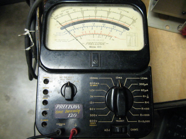
(As you see the left side has AC spot DC spot when used on special 600 volt setting, at bottom)
5th question: It is not real clear in some of the earlier pics, but if you were to trace the black wire (between the red and tan wires on the red plug that has the black jumper as well) it goes absolutely nowhere. If you apply low 1.5 v (single battery) the "x" drive it turns slow and apply 2 batteries goes quite a bit quicker.
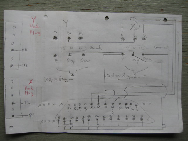
The pic above is not my best work,as you see P1 AND P2; if you apply positive battery voltage to P1 it turns clockwise (looking at the face of motor); if you apply positive battery voltage to P2 it turns counter-clockwise (looking at the face of motor)
6th question: with the jumper removed there is no motion at all.
7th question: see question 5.
My plan is to connect wires as per prior post #75047:
If they are an enable, and they are DC current, less than 100v and 50mA, you could connect the one for the X, positive wire to TB5 pin2 on the 7i77 and the negative wire to TB5 pin1.
Once you have a basic config, set up for Linuxcnc, the first thing you want to do is test the encoders. I'd suggest leaving the amps disconnected at this point. Once you have the encoders working (turning the motor moves the DRO in Linuxcnc). Then you are ready to try the amps. You could enable the amp and apply a small voltage with a battery (think AA or C battery), see if the motor turns. This might give a clue how you should connect the analog wires to the 7i77. Then you are ready to test the amp connected. Be prepared for a runaway (the odds of it happening is at least 50/50).
Once everything is connected you are ready to do a little tuning. Read some of the tutorials about servo tuning.
Many many thanks!
Chris
As to respond to 1st & 2nd question, as the pic shows the lights are located on the edge of the enclosure and did not change during the testing.
3nd question: for those that did not know how to test for AC or DC look at your meter (if a professional grade equipment) and you will see a separate dedicated spot to connect one of the probes that will allow you to tease out with type of voltage you are dealing with, then use the appropriate scale for accurate voltage assessment as far as voltage values.
4th question: The needle was at the(180 OHMS) top scale on (12 MA setting at the multi-select)
(As you see the left side has AC spot DC spot when used on special 600 volt setting, at bottom)
5th question: It is not real clear in some of the earlier pics, but if you were to trace the black wire (between the red and tan wires on the red plug that has the black jumper as well) it goes absolutely nowhere. If you apply low 1.5 v (single battery) the "x" drive it turns slow and apply 2 batteries goes quite a bit quicker.
The pic above is not my best work,as you see P1 AND P2; if you apply positive battery voltage to P1 it turns clockwise (looking at the face of motor); if you apply positive battery voltage to P2 it turns counter-clockwise (looking at the face of motor)
6th question: with the jumper removed there is no motion at all.
7th question: see question 5.
My plan is to connect wires as per prior post #75047:
If they are an enable, and they are DC current, less than 100v and 50mA, you could connect the one for the X, positive wire to TB5 pin2 on the 7i77 and the negative wire to TB5 pin1.
Once you have a basic config, set up for Linuxcnc, the first thing you want to do is test the encoders. I'd suggest leaving the amps disconnected at this point. Once you have the encoders working (turning the motor moves the DRO in Linuxcnc). Then you are ready to try the amps. You could enable the amp and apply a small voltage with a battery (think AA or C battery), see if the motor turns. This might give a clue how you should connect the analog wires to the 7i77. Then you are ready to test the amp connected. Be prepared for a runaway (the odds of it happening is at least 50/50).
Once everything is connected you are ready to do a little tuning. Read some of the tutorials about servo tuning.
Many many thanks!
Chris
Last edit: 27 May 2016 16:14 by new2linux.
Please Log in or Create an account to join the conversation.
- Todd Zuercher
-
- Away
- Platinum Member
-
Less
More
- Posts: 4963
- Thank you received: 1369
27 May 2016 16:22 #75165
by Todd Zuercher
Replied by Todd Zuercher on topic retrofit Bridgeport Prototrak Plus
Congratulations, it sounds like things are starting to come together for you.
The following user(s) said Thank You: new2linux
Please Log in or Create an account to join the conversation.
28 May 2016 16:24 - 28 May 2016 16:24 #75189
by new2linux
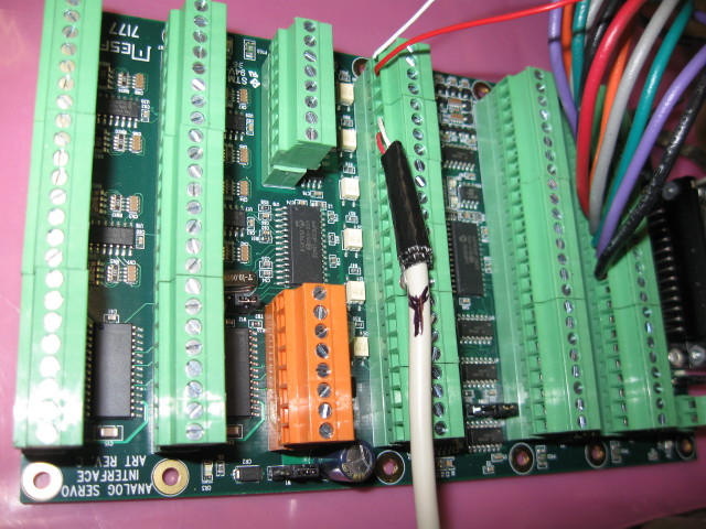
This is the most recent pic of the 7i77 with input from power supply amplifier. Soon I will power up for 1st time.
Many, many thanks to all!
Replied by new2linux on topic retrofit Bridgeport Prototrak Plus
This is the most recent pic of the 7i77 with input from power supply amplifier. Soon I will power up for 1st time.
Many, many thanks to all!
Last edit: 28 May 2016 16:24 by new2linux.
Please Log in or Create an account to join the conversation.
03 Jun 2016 14:23 - 05 Jun 2016 00:37 #75429
by new2linux
Replied by new2linux on topic retrofit Bridgeport Prototrak Plus
Attached is a screenshot of errors that I am unable to get past. Any help would be most appreciated and any logic to how to understand what the problem is would also be helpful.
Many thanks!
Many thanks!
Last edit: 05 Jun 2016 00:37 by new2linux. Reason: latest and greatest
Please Log in or Create an account to join the conversation.

03 Jun 2016 14:29 #75430
by andypugh
Replied by andypugh on topic retrofit Bridgeport Prototrak Plus
We need the lines further down.
Press, the "Select all" button and copy/paste the whole error report into a text file and attach it.
Press, the "Select all" button and copy/paste the whole error report into a text file and attach it.
Please Log in or Create an account to join the conversation.
Moderators: piasdom
Time to create page: 1.077 seconds