Create variables in function of kinematics values
- jstoquica
-
 Topic Author
- Offline
- Premium Member
-

- Posts: 137
- Thank you received: 9
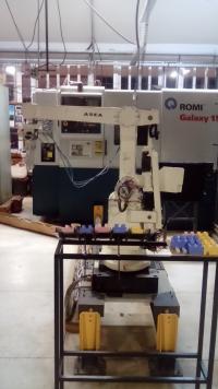
Recently I did a simulation of robotic manipulator with 5 DOF. A simulation was made in vismach, with a new kinematics definition. Now, the next step is migrate the new configuration to the physical robot with the linuxcnc advantages. But, I have a doubt with the real implementation. The inverse kinematic has the relation with the links like if each servo-motor was in the appropriate link to generate a robot motion. However, it's not like that, the motor are located away of each joint, the motion transmission is by gears and linear actuators, like you can see in the image.

I have the relationship equation of the displacement of motors in function of the angles (theta) generated by inverse kinematics computations. So, I need the motors values for the real implementation and the angles (theta) values for simulation and relationship equations.
When the *.c file is compiled, it generate the angles values (inverse kinematics):
   joint[0] = th1*180/PM_PI;
   joint[1] = th2*180/PM_PI;
   joint[2] = th3*180/PM_PI;
   joint[3] = th4*180/PM_PI;
   joint[4] = th5*180/PM_PI;
But I don't know, how can I manage this variables in the HAL file with simulation and real implementation. I think that I can add the relationship equations (motors and joint angles) in the *.c file, to compute the displacement motor values, but again I don't know how in the HAL file invoke them to generate the signals for the parallel card (who controls the motors through gecko drives). Recently, I can integrate one DOF with the simulation in vismach and one real motor, but the real application is different because the values are different too.
Thanks for your time and suggestions.
Please Log in or Create an account to join the conversation.
- andypugh
-

- Offline
- Moderator
-

- Posts: 23550
- Thank you received: 5018
However, it looks like that might not be the case.
Are there encoders in the joints? (how big is the robot, it looks like it might be tiny?)
The output of the kinematics through the motion component is an angle in degrees. You could consider modifying this using the lincurve HAL component to change the steps-per-degree as a function of requested motor position. Alternatively you could modify the kinematics file to incorporate the nonlinearity.
Some sample kinematics files do include code that creates HAL pins, and makes the value available to the kinematics. it is surprisingly straightforward. This is an example from 5axiskins.
114     result = hal_pin_float_new("5axiskins.pivot-length", HAL_IO, &(haldata->pivot_length), comp_id);
 115     if(result < 0) goto error'
This creates a variable that can be used in calculations and which will always hold the value from HAL. (What actually happens is that the address of the variable is changed so that it points to a shared-memory area that other HAL pins write to).
There is a bit of complexity in that the variable must be a pointer, and is wrapped in a struct that makes is possible to hal_malloc it. This is not 100% necessary, but allows for easier expansionof the number of pins.
You can see the value being usd in a calculation here:
48 pos->tran.z = joints[2] + *(haldata->pivot_length) + r.z;Please Log in or Create an account to join the conversation.
- jstoquica
-
Topic Author
- Offline
- Premium Member
-
- Posts: 137
- Thank you received: 9
If the relationship between joint angles and motor turns is linear then it is purely a matter of setting the correct scale for the step generator to give the correct steps per degree.
However, it looks like that might not be the case.
Yes, It's not the case.
Are there encoders in the joints? (how big is the robot, it looks like it might be tiny?)
The encoders aren't in the joints, are located in each motor, away from the joints. The size of the robot from the floor to the third axis (like the image) is approx. 1.2 mt.
The output of the kinematics through the motion component is an angle in degrees. You could consider modifying this using the lincurve HAL component to change the steps-per-degree as a function of requested motor position. Alternatively you could modify the kinematics file to incorporate the non-linearity.
It's right, the outputs of the kinematics are in degrees, and the results relationship equations are en degrees too. If I only want to do the movement of the real motor, just for each variable joint[0] to joint[4] will add the relationship with the motors, like this:
th1=th1*180/PM_PI;
joint[0] = (th1 - alpha1) / k1;

//where alpha1 and k1 variables of the robot, like reduction gear and offset constant respectively.
But I want to use the simulation that was made in vismach and the integration with the real robot. Therefore I think I need for that, 5 variables like joint to control the real motors and 5 variables like joint too, to control simulation motors.
I still don't understand how in the HAL file I can see the interaction with the kinematics variables (joint[0]->[4]), linuxcnc does the relationship like:
AXIS_0 -> joint[0]
AXIS_1 -> joint[1]
...
AXIS_4 -> joint[4] ?
I hope to make clear my idea for receive your suggestions. Regards.
Please Log in or Create an account to join the conversation.
- andypugh
-
- Offline
- Moderator
-
- Posts: 23550
- Thank you received: 5018
But I want to use the simulation that was made in vismach and the integration with the real robot.
One option would be to modify the Vismach model to be a more exact copy of the real robot. (This might be difficult).
Alternatively, your kinematics could perform the calculation of joint angles from actuator positions (this is probably necessary anyway) and output those values to HAL. You would link these angles to the Vismach model rather than the axis.N.motor-position-cmd signals.
You probably want those output pins from the kinematics anyway, for troubleshooting.
Please Log in or Create an account to join the conversation.
- jstoquica
-
Topic Author
- Offline
- Premium Member
-
- Posts: 137
- Thank you received: 9
andypugh wrote:
Alternatively, your kinematics could perform the calculation of joint angles from actuator positions (this is probably necessary anyway) and output those values to HAL. You would link these angles to the Vismach model rather than the axis.N.motor-position-cmd signals.
But I need 5 additional for control the real motors. I have in the kinematics file (*.c) the joint angles variables:
joint[0] = th1 * (relationship equations for motor1);
joint[1] = th2 * (relationship equations for motor2);
joint[2] = th3 * (relationship equations for motor3) ;
joint[3] = th4 * (relationship equations for motor4);
joint[4] = th5 * (relationship equations for motor5);
That initially will control the real motors with something like that in the HAL file for the 5 degrees of freedom of the robot:
(...)
setp stepgen.0.position-scale [AXIS_0]SCALE
setp stepgen.0.steplen 1
setp stepgen.0.stepspace 0
setp stepgen.0.dirhold 15200
setp stepgen.0.dirsetup 15200
setp stepgen.0.maxaccel [AXIS_0]STEPGEN_MAXACCEL
net xpos-cmd axis.0.motor-pos-cmd => stepgen.0.position-cmd
net xpos-fb stepgen.0.position-fb => axis.0.motor-pos-fb
net xstep <= stepgen.0.step
net xdir <= stepgen.0.dir
net xenable axis.0.amp-enable-out => stepgen.0.enable
(...)
And for the simulation in vismach I need 5 additional variables with original theta values, but I dont know how create them in the *.c file and like these angles to the vismach model. It's possible create in the *.c file 5 additional variables like:
joint[0] = th1 * (relationship equations for motor1);
joint[1] = th2 * (relationship equations for motor2);
joint[2] = th3 * (relationship equations for motor3) ;
joint[3] = th4 * (relationship equations for motor4);
joint[4] = th5 * (relationship equations for motor5);

joint[5] = th1;
joint[6] = th2;
joint[7] = th3;
joint[8] = th4;
joint[9] = th5;
And then in the HAL file link these variables to the vismach model with something like this?:
axis.5.motor-position-cmd;
axis.6.motor-position-cmd:
axis.7.motor-position-cmd;
axis.8.motor-position-cmd;
axis.9.motor-position-cmd;
Appreciate your helpful for solve this issue for as 5 variables of real motor and 5 variables for vismach model (because are different values)
Please Log in or Create an account to join the conversation.
- andypugh
-
- Offline
- Moderator
-
- Posts: 23550
- Thank you received: 5018
Look back at the example from 5axiskins in #62863
What you would do is create a set of 5 thetas in a hal data struct: (see git.linuxcnc.org/gitweb?p=linuxcnc.git;a...80e5de935e15;hb=HEAD for 5axiskins where I am copying from)
struct haldata {
     hal_float_t  *th1;
     hal_float_t  *th2;
     hal_float_t  *th3;
     hal_float_t  *th4;
     hal_float_t  *th5;
 } *haldata;
Then make the variables into HAL pins:
haldata = hal_malloc(sizeof(struct haldata));
result = hal_pin_float_new("aseakins.theta1", HAL_IO, &(haldata->th1), comp_id);
if(result < 0) goto error;
result = hal_pin_float_new("aseakins.theta2", HAL_IO, &(haldata->th2), comp_id);
if(result < 0) goto error;
result = hal_pin_float_new("aseakins.theta3", HAL_IO, &(haldata->th3), comp_id);
if(result < 0) goto error;
result = hal_pin_float_new("aseakins.theta4", HAL_IO, &(haldata->th4), comp_id);
if(result < 0) goto error;
result = hal_pin_float_new("aseakins.theta5", HAL_IO, &(haldata->th5), comp_id);
if(result < 0) goto error;
*(haldata->th1) = 180;
*(haldata->th2) = 180;
*(haldata->th3) = 0;
*(haldata->th4) = 180;
*(haldata->th5) = 90;

hal_ready(comp_id);
return 0;
Then use those variables in your calculations
*(haldata->th1) = pos->tran.x * complex calculations
joint[0] = *(haldata->th1) * anothr_complex_calulation
...
And then in HAL:
net xpos-cmd axis.0.motor-pos-cmd => stepgen.0.position-cmd
net xpos-theta aseakins.theta1 => aseagui.joint-0
Please Log in or Create an account to join the conversation.
- jstoquica
-
Topic Author
- Offline
- Premium Member
-
- Posts: 137
- Thank you received: 9
Only one more question:
When you say in HAL:
net xpos-cmd axis.0.motor-pos-cmd => stepgen.0.position-cmdObviously, it's for the motors with the others appropriate code lines.
But in the next line for the vismach model:
net xpos-theta aseakins.theta1 => aseagui.joint-0aseakins.theta1 is related to created variables in the *.c file. But How can I integrate it with HAL file default structure ? Can I do it like this?
net J0pos aseakins.theta1
net J1pos aseakins.theta2
net J2pos aseakins.theta3
net J3pos aseakins.theta4
net J4pos aseakins.theta5

loadrt scale count=5

addf scale.0 servo-thread
addf scale.1 servo-thread
addf scale.2 servo-thread
addf scale.3 servo-thread
addf scale.4 servo-thread

net J0pos scale.0.in
net J1pos scale.1.in
net J2pos scale.2.in
net J3pos scale.3.in
net J4pos scale.4.in

setp scale.0.gain 1
setp scale.1.gain 1
setp scale.2.gain 1
setp scale.3.gain 1
setp scale.4.gain 1

net J0scaled scale.0.out irb-gui.joint1
net J1scaled scale.1.out irb-gui.joint2
net J2scaled scale.2.out irb-gui.joint3
net J3scaled scale.3.out irb-gui.joint4
net J4scaled scale.4.out irb-gui.joint5
Or only add for control vismach model:
net J0pos aseakins.theta1 => irb-gui.joint1
net J1pos aseakins.theta2 => irb-gui.joint2
net J2pos aseakins.theta3 => irb-gui.joint3
net J3pos aseakins.theta4 => irb-gui.joint4
net J4pos aseakins.theta5 => irb-gui.joint5
Regards.
Please Log in or Create an account to join the conversation.
- andypugh
-
- Offline
- Moderator
-
- Posts: 23550
- Thank you received: 5018
aseakins.theta1 is related to created variables in the *.c file. But How can I integrate it with HAL file default structure
Just like any other pin, you can do all the same things.
However, not if you copy my code exactly, because I messed up slightly. The HAL pins created in the kins module need to be dedicated outputs. If they are IO pins then they won't work properly.
Details here:
www.linuxcnc.org/docs/html/man/man3/hal_pin_float_new.3hal.html
All the rest are near the bottom of the page here, under "API calls: HAL"
Please Log in or Create an account to join the conversation.
- jstoquica
-
Topic Author
- Offline
- Premium Member
-
- Posts: 137
- Thank you received: 9
I did the modifications for *.c file, creating the new 5 variables with HAL structure, then the compile process was success.
But when modify the HAL file and run the simulation, fail my non-logical attempt., because I don't know how link the motion module with the new HAL pins to move the vismach model. Motion module pins like axis.0.motor-pos-cmd or axis.0.motor-pos-fb.
# load RT modules
loadrt irb
loadrt [EMCMOT]EMCMOT servo_period_nsec=[EMCMOT]SERVO_PERIOD traj_period_nsec=[EMCMOT]TRAJ_PERIOD num_joints=[TRAJ]AXES

#add motion controller functions to servo thread
addf motion-command-handler servo-thread
addf motion-controller servo-thread

# create HAL signals for position commands from motion module
net J0pos <= axis.0.motor-pos-cmd
net J1pos <= axis.1.motor-pos-cmd
net J2pos <= axis.2.motor-pos-cmd
net J3pos <= axis.3.motor-pos-cmd
net J4pos <= axis.4.motor-pos-cmd


# loop position commands back to motion module feedback
net J0pos => axis.0.motor-pos-fb
net J1pos => axis.1.motor-pos-fb
net J2pos => axis.2.motor-pos-fb
net J3pos => axis.3.motor-pos-fb
net J4pos => axis.4.motor-pos-fb

#net J0pos <= irb.th1
#net J1pos <= irb.th2
#net J2pos <= irb.th3
#net J3pos <= irb.th4
#net J4pos <= irb.th5


# estop loopback
net estop-loop iocontrol.0.user-enable-out iocontrol.0.emc-enable-in

# create signals for tool loading loopback
net tool-prep-loop iocontrol.0.tool-prepare iocontrol.0.tool-prepared
net tool-change-loop iocontrol.0.tool-change iocontrol.0.tool-changed

loadusr -W irbgui

loadrt scale count=5

addf scale.0 servo-thread
addf scale.1 servo-thread
addf scale.2 servo-thread
addf scale.3 servo-thread
addf scale.4 servo-thread

net J0pos scale.0.in
net J1pos scale.1.in
net J2pos scale.2.in
net J3pos scale.3.in
net J4pos scale.4.in

setp scale.0.gain 1
setp scale.1.gain 1
setp scale.2.gain 1
setp scale.3.gain 1
setp scale.4.gain 1

net J0scaled scale.0.out irbgui.joint0
net J1scaled scale.1.out irbgui.joint1
net J2scaled scale.2.out irbgui.joint2
net J3scaled scale.3.out irbgui.joint3
net J4scaled scale.4.out irbgui.joint4
What can I do for link the new variables irb.th# with the motion module? I think to create in the INI file 5 additional axis, but It's a rude and undesirable solution....
regards.
Please Log in or Create an account to join the conversation.
- andypugh
-
- Offline
- Moderator
-
- Posts: 23550
- Thank you received: 5018
What can I do for link the new variables irb.th# with the motion module?.
Just don't.
In the kinematics file joint[0] goes to the motion module, has backlash compensation applied, etc, then comes out as axis.0.motor-position-cmd.
You want to pass the unmodified theta value to the Vismach model, so just connect irb.th* directly to the Vismach model.
Please Log in or Create an account to join the conversation.