7i92, laser power velocity controlled
- Ralfh
- Offline
- Junior Member
-

Less
More
- Posts: 22
- Thank you received: 10
31 Dec 2019 13:35 #153603
by Ralfh
7i92, laser power velocity controlled was created by Ralfh
Hi,
i have a few questions regarding the hal configuration for my current project: laser vector engraving.
I already managed to hook up a 2,5W laser to my 7i92, changed a few lines in a Fusion360 Postprocessor and can engrave with on/off commands.
The Postprocessor uses the 2D-Contour CAM module for plasma/waterjet/laser and simply turns on/off the laser with M62/M65. Postprocessor attached. Heres an example of my first laser engraving:
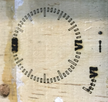
As you can see, the rectangles look ok, but the numbers are way too burnt. I think the problem is that there are too many lines with too many accelerations/decelerations in one spot. I think i can just model with fewer lines, but the acceleration and deceleration will still be a problem. To compensate for slower movements, i need to lower the laser power.
My next step would be to use a PWM to control my laser power. I would net my velocity to that PWM, If the velocity is high the laser power is high - if the velocity is small, the laser power is low. Everytime M62/M65 would come up the PWM gets enabled/disabled.
Since this is my first fairly complex hal experience, i would like to discuss it here. Does this hal-snippet looks somehow of what i described?
For testing i will set pwm_scale to 0.0017 since my max linear velocity is 34mm/s, which should result in the maximum PWM frequency and maximum laser power.
i have a few questions regarding the hal configuration for my current project: laser vector engraving.
I already managed to hook up a 2,5W laser to my 7i92, changed a few lines in a Fusion360 Postprocessor and can engrave with on/off commands.
The Postprocessor uses the 2D-Contour CAM module for plasma/waterjet/laser and simply turns on/off the laser with M62/M65. Postprocessor attached. Heres an example of my first laser engraving:
As you can see, the rectangles look ok, but the numbers are way too burnt. I think the problem is that there are too many lines with too many accelerations/decelerations in one spot. I think i can just model with fewer lines, but the acceleration and deceleration will still be a problem. To compensate for slower movements, i need to lower the laser power.
My next step would be to use a PWM to control my laser power. I would net my velocity to that PWM, If the velocity is high the laser power is high - if the velocity is small, the laser power is low. Everytime M62/M65 would come up the PWM gets enabled/disabled.
Since this is my first fairly complex hal experience, i would like to discuss it here. Does this hal-snippet looks somehow of what i described?
loadrt num_dio=1 num_pwm=2

setp hm2_7i92.0.pwmgen.01.enable 0                           #BIT enable PWM
setp hm2_7i92.0.pwmgen.01.pwm_frequency 20000    #float set ALL PWM frequencies
setp hm2_7i92.0.pwmgen.01.scale 0.0017                    #float Scaling factor to convert ’value’ from arbitrary units to duty cycle: dc = value / scale.
setp hm2_7i92.0.pwmgen.01.scale.output−type 1         #1(PWM on Out0 and Direction on Out1)

net laserintensity motion.current-vel => hm2_7i92.0.pwmgen.01.value  #FLOAT to FLOAT, current velocity to PWM
net laseron motion.digital-out-00 => hm2_7i92.0.pwmgen.01.enable     #BIT to BIT, When M62 is sent, PWM starts; when M65 is sent, PWM stops
For testing i will set pwm_scale to 0.0017 since my max linear velocity is 34mm/s, which should result in the maximum PWM frequency and maximum laser power.
Please Log in or Create an account to join the conversation.
- PCW
-

- Away
- Moderator
-

Less
More
- Posts: 17996
- Thank you received: 5283
31 Dec 2019 14:49 - 31 Dec 2019 14:52 #153604
by PCW
Replied by PCW on topic 7i92, laser power velocity controlled
it looks close though the PWM scale should be something like maximum velocity
(in machine units/second) so you get 100% duty cycle at full speed.
( a scale of 0.0017 would mean full PWM at any velocity >= 0.0017 mm/s)
It might be helpful to use the scale component because it has an offset
and I would expect the PWM control of the laser vs marking to be quite
non-linear. If more complex linearization is needed, the lincurve component
could be used.
Last edit: 31 Dec 2019 14:52 by PCW.
The following user(s) said Thank You: Ralfh
Please Log in or Create an account to join the conversation.
- rodw
-

- Offline
- Platinum Member
-

Less
More
- Posts: 12054
- Thank you received: 4114
01 Jan 2020 00:38 #153674
by rodw
Replied by rodw on topic 7i92, laser power velocity controlled
This could be easilly managed via custom component or as PCW says lincurve by monitoring motion.current−vel
The trick though you will need to add a remap on the F command so you can save the commanded velocity using M67/M68 as currently Linuxcnc has no way of telling HAL what that was.
So then its a simple matter to apply a PWM adjustment based on the percentage of commanded velocity if current_vel < commanded velocity.
Please Log in or Create an account to join the conversation.
- PCW
-
- Away
- Moderator
-
Less
More
- Posts: 17996
- Thank you received: 5283
01 Jan 2020 02:35 #153687
by PCW
Replied by PCW on topic 7i92, laser power velocity controlled
What is the advantage of making the laser exposure (inversely) proportional to the feed rate?
Once you have the PWM vs velocity correct for a given burn depth it seems like you would not want mess with it...
Once you have the PWM vs velocity correct for a given burn depth it seems like you would not want mess with it...
Please Log in or Create an account to join the conversation.
- rodw
-
- Offline
- Platinum Member
-
Less
More
- Posts: 12054
- Thank you received: 4114
01 Jan 2020 02:52 - 01 Jan 2020 02:54 #153690
by rodw
Well I might be a bit out of my depth here but its very similar to a problem we encountered with plasma machines pre-plasmac which was compounded by errors in the documents (since corrected on our feedback). The issue was around THC velocity lock which we initially tied to current-vel instead of commanded-vel so we got dives when encountering slow segments becasue the THC velocity lock never came on or was re-enabled at slow velocities unexpecredly
If only someone could push state tags branch there would be much cleaner solutions as we would know commanded-vel.
Wouldn't you have different PWM settings and feedrates for different materials? If so, wouldn't this be more flexible?
Replied by rodw on topic 7i92, laser power velocity controlled
What is the advantage of making the laser exposure (inversely) proportional to the feed rate?
Once you have the PWM vs velocity correct for a given burn depth it seems like you would not want mess with it...
Well I might be a bit out of my depth here but its very similar to a problem we encountered with plasma machines pre-plasmac which was compounded by errors in the documents (since corrected on our feedback). The issue was around THC velocity lock which we initially tied to current-vel instead of commanded-vel so we got dives when encountering slow segments becasue the THC velocity lock never came on or was re-enabled at slow velocities unexpecredly
If only someone could push state tags branch there would be much cleaner solutions as we would know commanded-vel.
Wouldn't you have different PWM settings and feedrates for different materials? If so, wouldn't this be more flexible?
Last edit: 01 Jan 2020 02:54 by rodw.
Please Log in or Create an account to join the conversation.
- PCW
-
- Away
- Moderator
-
Less
More
- Posts: 17996
- Thank you received: 5283
01 Jan 2020 03:01 #153691
by PCW
Replied by PCW on topic 7i92, laser power velocity controlled
I suspect you might need different velocity/PWM curves for different materials and speeds,
depending on how fussy you are.
I don't think you have the same issues as corner lock since there is no height control to manage.
depending on how fussy you are.
I don't think you have the same issues as corner lock since there is no height control to manage.
Please Log in or Create an account to join the conversation.
- rodw
-
- Offline
- Platinum Member
-
Less
More
- Posts: 12054
- Thank you received: 4114
01 Jan 2020 04:04 #153693
by rodw
Understood there is no need for Corner lock but the same variables are in use and you need to remap the Gcode F command to capture the commanded velocity.
Replied by rodw on topic 7i92, laser power velocity controlled
I suspect you might need different velocity/PWM curves for different materials and speeds,
depending on how fussy you are.
I don't think you have the same issues as corner lock since there is no height control to manage.
Understood there is no need for Corner lock but the same variables are in use and you need to remap the Gcode F command to capture the commanded velocity.
Please Log in or Create an account to join the conversation.
- rodw
-
- Offline
- Platinum Member
-
Less
More
- Posts: 12054
- Thank you received: 4114
01 Jan 2020 04:07 #153694
by rodw
Replied by rodw on topic 7i92, laser power velocity controlled
We might be at cross purposes here Peter. I was thinking you would calibrate based on straight line cuts at commanded velocity for each material and then adjust the PWM downwards to some algorithm based on current velocity....
Please Log in or Create an account to join the conversation.
- PCW
-
- Away
- Moderator
-
Less
More
- Posts: 17996
- Thank you received: 5283
01 Jan 2020 04:08 - 01 Jan 2020 04:13 #153695
by PCW
Replied by PCW on topic 7i92, laser power velocity controlled
My point was that I did not see the need for the commanded velocity, only the current velocity
since the absolute laser exposure could be preset with just that information
since the absolute laser exposure could be preset with just that information
Last edit: 01 Jan 2020 04:13 by PCW.
Please Log in or Create an account to join the conversation.
- Ralfh
- Offline
- Junior Member
-
Less
More
- Posts: 22
- Thank you received: 10
08 Jan 2020 09:35 #154295
by Ralfh
Replied by Ralfh on topic 7i92, laser power velocity controlled
Thanks! I finally got to my shop and tested it. Some lines were incorrect or unnecessary, here is my current hal snippet:
Here is the result of that:
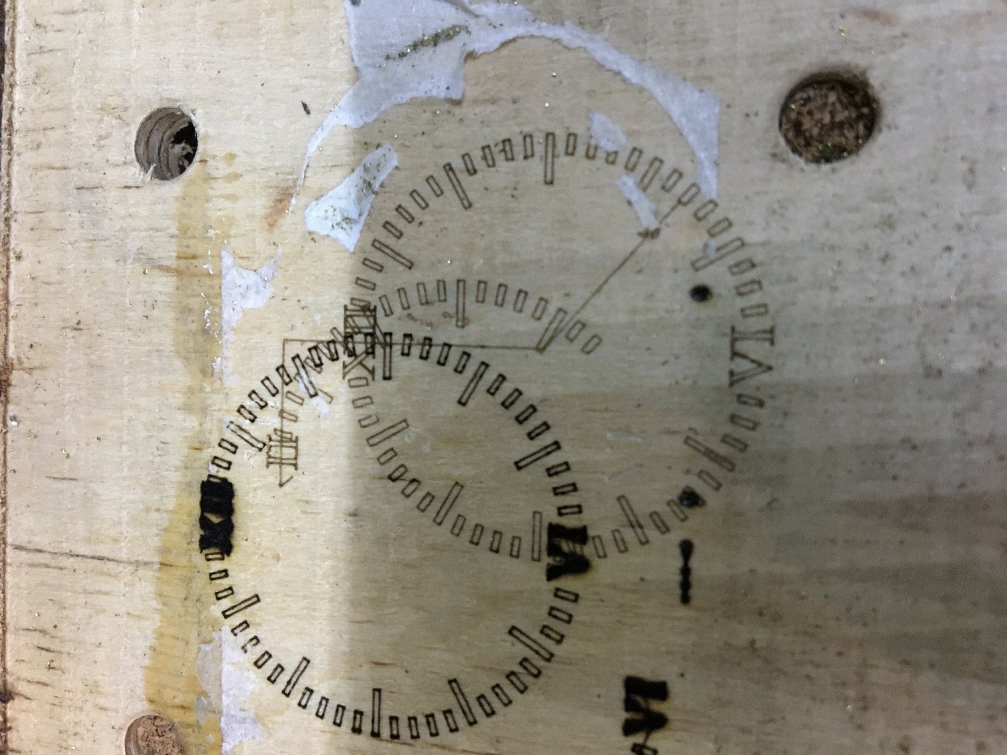
I need to do way more testing and fiddling, but that second engraving looks quite promising.
What i noticed:
loadrt num_dio=1
loadrt hm2_eth board_ip="192.168.1.121" config=" num_encoders=2 num_pwmgens=2 num_stepgens=4"

setp hm2_7i92.0.pwmgen.01.enable 0              #BIT enable PWM
setp hm2_7i92.0.pwmgen.pwm_frequency 20000       #float set ALL PWM frequencies
setp hm2_7i92.0.pwmgen.01.scale 34              #float Scaling factor to convert value from arbitrary units to duty cycle: dc = value / scale.

net laserintensity motion.current-vel => hm2_7i92.0.pwmgen.01.value #current velocity to PWM 1=1
net laseron motion.digital-out-00 => hm2_7i92.0.pwmgen.01.enable #When M62 is sent, PWM starts; when M65 is sent, PWM stops
Here is the result of that:
I need to do way more testing and fiddling, but that second engraving looks quite promising.
What i noticed:
- If my machine is stopped while it engraves, the laser turns "off". Thats because my velocity is 0 -> PWM is 0 -> laser power 0
- That may lead to dangerous situations where i emergency stop the machine, the laser looks like it's off, but if i jog afterwards it turns on. See the straight lines between the engravings. In short term i will use a external power switch for the laser for that
- The laser power looks like it's way weaker than the original engraving.
- I had a scale of 34, a max speed of 34mm/s but only engraved with 17mm/s, so there was only a 50% PWM output
- I will need to do more testing with my speeds, scale, maybe the offset parameters or lincurve.
Attachments:
Please Log in or Create an account to join the conversation.
Time to create page: 0.244 seconds