7i92, laser power velocity controlled
- Todd Zuercher
-

- Away
- Platinum Member
-

Less
More
- Posts: 4696
- Thank you received: 1439
08 Jan 2020 14:04 #154309
by Todd Zuercher
Replied by Todd Zuercher on topic 7i92, laser power velocity controlled
Adding an indicator light of some sort to the machine to show that the laser is on/enabled would not be difficult, and might be a very good idea. Also adding hal connections and or physical connections to disable the laser when in e-stop would be wise and not difficult.
Please Log in or Create an account to join the conversation.
- PCW
-

- Offline
- Moderator
-

Less
More
- Posts: 17680
- Thank you received: 5170
08 Jan 2020 16:02 #154315
by PCW
Replied by PCW on topic 7i92, laser power velocity controlled
In addition, for safety, the PWM polarity should be such that a high output from the 7I92 disables the laser (this means using active low PWM), otherwise the laser may turn on at power up or after a watchdog bite.
Please Log in or Create an account to join the conversation.
- Ralfh
- Offline
- Junior Member
-

Less
More
- Posts: 22
- Thank you received: 10
09 Jan 2020 07:25 #154411
by Ralfh
Replied by Ralfh on topic 7i92, laser power velocity controlled
I got to test a few things yesterday, but first my current workflow for safety:
For now that is OK for me. In short terms i will use the LED on my powersupply as an indicator, in long terms i would like to test the active low PWM like described here: active low PWM
Now to the fun part:
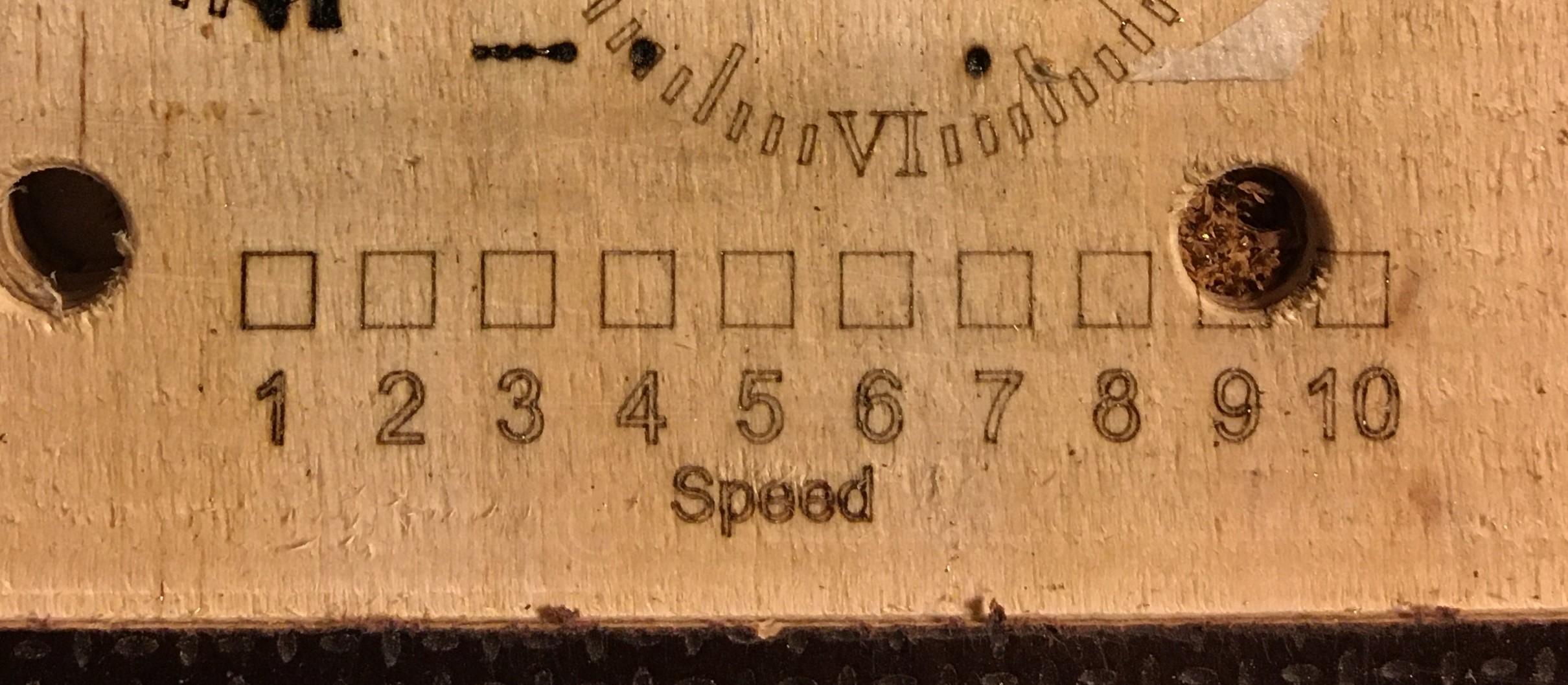
I tested my PWM output and velocity linearity. I engraved a rectangle and a number where number 1 is engraved with 10% velocity, number 2 is 20% velocity and so on.
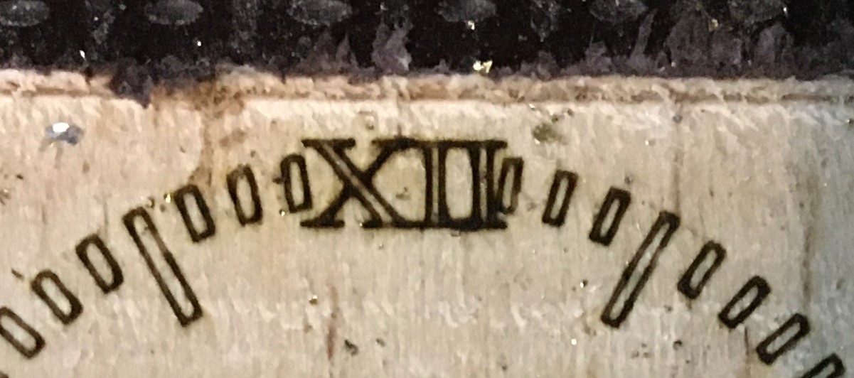
Number 1 looks way too burnt, number 7 a little weak. But all in all pretty linear. This is for now more than acceptable for my application. (engraving clock-faces)
As a reference: the rectangles are 0,5mm thick. The laser burn width is about 0,15mm.
- I install the Laser on my machine
- I start my machine
- I load my Laser NC-code
- I put on my glasses
- I apply power to the laser
- I start the program
- I turn off the power to the laser after the program is finished or when it stops
For now that is OK for me. In short terms i will use the LED on my powersupply as an indicator, in long terms i would like to test the active low PWM like described here: active low PWM
Now to the fun part:
I tested my PWM output and velocity linearity. I engraved a rectangle and a number where number 1 is engraved with 10% velocity, number 2 is 20% velocity and so on.
Number 1 looks way too burnt, number 7 a little weak. But all in all pretty linear. This is for now more than acceptable for my application. (engraving clock-faces)
As a reference: the rectangles are 0,5mm thick. The laser burn width is about 0,15mm.
Attachments:
Please Log in or Create an account to join the conversation.
Time to create page: 0.560 seconds


