How Linuxcnc is compensating backlash?
- boksi
- Offline
- Junior Member
-

Less
More
- Posts: 27
- Thank you received: 0
05 Oct 2020 20:42 #185005
by boksi
How Linuxcnc is compensating backlash? was created by boksi
I am wondering about how is backlash compensation implemented in linuxcnc engine. Is it done on the fly or all axes has to stop until backlash compensation is applied to current one which changed direction?
If it is done on the fly, for higher values of backlash shouldn’t be there any irregularities on produced part?
Also wouldn’t be the similiar situation with closed loop with linear encoders? In this case backlash compensation would be turned off but closed loop with linear encoders could hide some portion of backlash smaller or higher and there would be always lost motion more-less.
If it is implemented like in second case are acc ramps up and down respected concerning axes which has to stop and then start again?
Also I have same questions for Mach3 and UCCNC.
Please Log in or Create an account to join the conversation.
- andypugh
-

- Offline
- Moderator
-

Less
More
- Posts: 19875
- Thank you received: 4642
06 Oct 2020 11:48 #185053
by andypugh
Replied by andypugh on topic How Linuxcnc is compensating backlash?
The answer is "imperfectly" ")
Basically when an axis reverses direction the motor is commanded to move backlash-distance in the new direction as quickly as possible,
That is all that it does.
It is better than nothing, but not a lot better than nothing.
It will typically work better with a lathe than a mill, as the cutting force directions are much more consistent with a lathe.
In fact I would say that you can make a perfectly acceptable lathe conversion with screw-mapping and the original screws, but I would always recommend switching to ballscrews on a mill.
Plasma ought to work OK with backlash comp too.
The following user(s) said Thank You: Aciera
Please Log in or Create an account to join the conversation.
- Todd Zuercher
-

- Away
- Platinum Member
-

Less
More
- Posts: 4757
- Thank you received: 1459
06 Oct 2020 18:00 #185106
by Todd Zuercher
Replied by Todd Zuercher on topic How Linuxcnc is compensating backlash?
On our wood carving machines, Linuxcnc's backlash compensation seems to cause more problems than it solves and I get better carving results with it turned off, even though these machines have a measurable amount of backlash.
Please Log in or Create an account to join the conversation.
- boksi
- Offline
- Junior Member
-
Less
More
- Posts: 27
- Thank you received: 0
06 Oct 2020 20:32 #185138
by boksi
Replied by boksi on topic How Linuxcnc is compensating backlash?
Thanks a both for answers. I am currently testing with dc motor, tacho directly coupled on motor shaft and linear encoder on axis which has 0.6mm backlash. I have also regular encoder on motor shaft but not using it currently. Loops are closed on drive level. Mechanic is old so fitting ball screws would be very complicated concerning time and work. Travel path is short (170mm) but has a lot of unequal distributed friction along and friciton differs a lot with direction change. With just linear encoder I get better results and lost motion is peak about 0.1 - 0.2 mm when changing direction (error is shape of triangle length about 150mS). Think this could be even lower with lowering acc slope and better controller tunning. It is question if current loop would give here any benefits or introduce a more noise and limit gains but I will test soon (motor has lot of inductance about 2.5mH so current loop could shorten time reaching desired torque). In this configuration motor reaches current position without hunting and stays steady as I can see and also checked by data from drive.
With dual loop I get little worse results as velocity loop is trying to handle nonlinear friction and has lot of ripple. Tacho signal is oscillating a lot around commanded value because of regulation - closed circle. I checked tacho signal with velocity loop only with motor (take a belt off) and it is clean and has ripple about 1-2% so I am sure the issue is not cable, noise or acquisition chain. Maybe this oscillation due friction could be handled by mapping connection velocity- oscillation frequency and configuring notch filters in real time. Also in this dual loop configuration motor hunts end position with slow-fast oscillation (depends of gains) between -0.03 and 0.03 mm.
With dual loop I get little worse results as velocity loop is trying to handle nonlinear friction and has lot of ripple. Tacho signal is oscillating a lot around commanded value because of regulation - closed circle. I checked tacho signal with velocity loop only with motor (take a belt off) and it is clean and has ripple about 1-2% so I am sure the issue is not cable, noise or acquisition chain. Maybe this oscillation due friction could be handled by mapping connection velocity- oscillation frequency and configuring notch filters in real time. Also in this dual loop configuration motor hunts end position with slow-fast oscillation (depends of gains) between -0.03 and 0.03 mm.
Please Log in or Create an account to join the conversation.
- Mike_Eitel
-

- Offline
- Platinum Member
-
Less
More
- Posts: 1052
- Thank you received: 183
07 Oct 2020 16:40 #185278
by Mike_Eitel
Replied by Mike_Eitel on topic How Linuxcnc is compensating backlash?
I think one thing around backlash is often overlooked. At least with my old mill and slow running spindle i had more chattering as the whole construction behaves like a resonating system with a "amplitude of the backlash" made 5he effort to swap to ball screws and i'm happy that i did.
Please Log in or Create an account to join the conversation.
- boksi
- Offline
- Junior Member
-
Less
More
- Posts: 27
- Thank you received: 0
07 Oct 2020 20:23 #185302
by boksi
Replied by boksi on topic How Linuxcnc is compensating backlash?
You are right. I tought little about this. Mill I have is Fritz Werner and weights about 1200kg. Table on axis I am currently reworking is more than 150kg and on that comes another axis with its table weighting also more than 150kg. Also there is a lot of friction. Did some test trying manually to move the table among direction that last time was moved as there should be seen backlash but it holds stiff. Plan is first to try light cuts to see how system responses and maybe I could get away without issues. I have read that conventional milling is better way for machines with backlash than climb milling concerning forces but I still not reached that point.
Please Log in or Create an account to join the conversation.
- scotth
- Away
- Elite Member
-

Less
More
- Posts: 242
- Thank you received: 61
08 Oct 2020 03:16 #185323
by scotth
Replied by scotth on topic How Linuxcnc is compensating backlash?
Backlash is a nice way to say dead band, the area where you have no control. Always try to fix it rather than trying to hide it. A climb cut will pull the axis through the non control area and cause chatter. Check your thrust bearings on your screw first, an indicator on the end of the screw will normally show motion. Next if you think it is the screw an indicator to a lead of the screw from the moving slide will show screw slack.
Please Log in or Create an account to join the conversation.
- BeagleBrainz
-

- Visitor
-

08 Oct 2020 03:44 #185324
by BeagleBrainz
Replied by BeagleBrainz on topic How Linuxcnc is compensating backlash?
Great explanation and wise words
Please Log in or Create an account to join the conversation.
- scotth
- Away
- Elite Member
-
Less
More
- Posts: 242
- Thank you received: 61
11 Oct 2020 22:22 #185768
by scotth
Replied by scotth on topic How Linuxcnc is compensating backlash?
Two things to look at that should help your problem. Go dual loop and that might help.
www.a-m-c.com/what-is-dual-loop-position...eeded/?cn-reloaded=1
granitedevices.com/wiki/Dual-loop_feedback_position_control
www.a-m-c.com/what-is-dual-loop-position...eeded/?cn-reloaded=1
granitedevices.com/wiki/Dual-loop_feedback_position_control
Please Log in or Create an account to join the conversation.
- boksi
- Offline
- Junior Member
-
Less
More
- Posts: 27
- Thank you received: 0
13 Oct 2020 21:42 - 13 Oct 2020 21:47 #186023
by boksi
Replied by boksi on topic How Linuxcnc is compensating backlash?
Thanks for info. I think that thrust bearings are ok as whole axis was taken apart and buld up again and checked. For now I tried turning in one direction with hand wheel then stop and pushed whole table into same direction. Quite a lot of force applied and it has moved. Start again turning hand wheel in same direction and it was loose as it needs to catch up with new position. Scale on hand wheel is in mm so I roughly measured backlash it is about 0.8mm until table starts moving and dial indicator showed that.
I am not currently working on this axis. I am working on axis which carries a lot more weight and couldn’t make same testing ( also this axis was taken apart and build up again so thrust bearings should be ok). Backlash here was measured with reading hand wheel and indicator while changing direction.
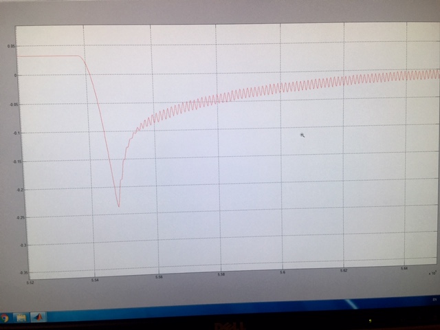
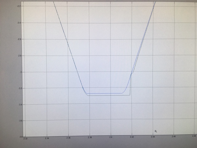
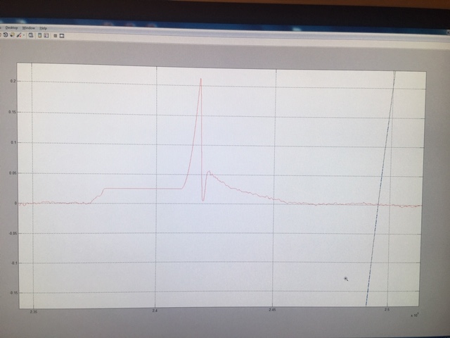
Concerning dual loop I posted results in post above here are some pictures of reference, output and error.
For inner loop I am using tacho.
Have to do a lot more concerning tuning but for now get a sense that glass scale is working “better” then dual loop with glass scale and tacho. Think this is due a lot of nonlinear friction so could not get high gains in inner speed loop so it is rather loose.
Here are plots glass scale + tacho (dual loop). Y axis is in mm x is in some time increment.
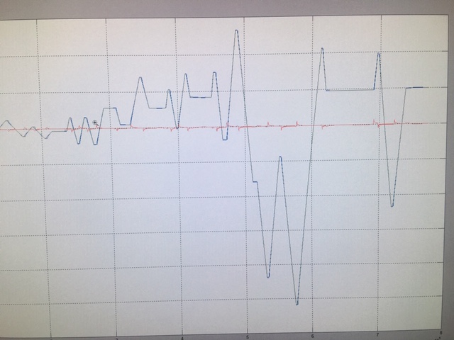
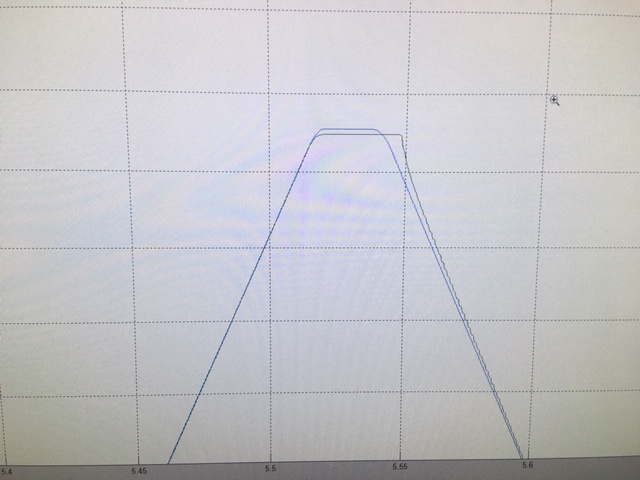
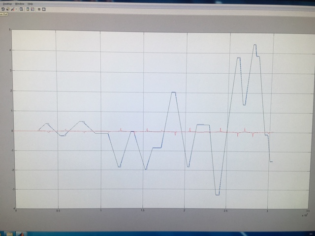
Here are plots closed loop with just glass scale.
I am not currently working on this axis. I am working on axis which carries a lot more weight and couldn’t make same testing ( also this axis was taken apart and build up again so thrust bearings should be ok). Backlash here was measured with reading hand wheel and indicator while changing direction.
Concerning dual loop I posted results in post above here are some pictures of reference, output and error.
For inner loop I am using tacho.
Have to do a lot more concerning tuning but for now get a sense that glass scale is working “better” then dual loop with glass scale and tacho. Think this is due a lot of nonlinear friction so could not get high gains in inner speed loop so it is rather loose.
Here are plots glass scale + tacho (dual loop). Y axis is in mm x is in some time increment.
Here are plots closed loop with just glass scale.
Attachments:
Last edit: 13 Oct 2020 21:47 by boksi.
Please Log in or Create an account to join the conversation.
Time to create page: 0.830 seconds