Kinematics for XYZAB mill
- Aciera
-

- Offline
- Administrator
-

Less
More
- Posts: 4717
- Thank you received: 2113
30 Nov 2022 09:53 - 30 Nov 2022 10:11 #258104
by Aciera
Replied by Aciera on topic Kinematics for XYZAB mill
(2) and (3) describe the four different matrices we have in our toolbox to model the kinematic chain of our machine. We can use translations T and rotations R around X,Y and Z respectively.
(5) shows the transformations that describe the XYZAC-TRT configuration of Figure 3 using some of the above four matrices in our toolbox :
First WAC being the translation from the workpiece to the pivot point (intersection of rotational axis of C and A)
Second CAA is the rotation around Z ie the C axis (note here that the minus sign of the Sc (sine(C) is switched because we are rotating the workpiece rather than the tool)
Third AAP is the rotation around X ie the A axis (note here that the minus sign of the Sc (sine(C) is switched because we are rotating the workpiece rather than the tool)
Fourth PAt is the translation from the pivot point to the tooltip ie the X,Y and Z axes
(6) and (7) show the individual matrices used in (5) and are not a modified 'formula' of (2) and (3)
[edit]
Damn editor just ditched all my formatting. I hope it makes at least somewhat sense.
[edit2]
Maybe I'm overdoing it now but here is an explanation why we use 4x4 matrices:
www.euclideanspace.com/maths/geometry/af.../matrix4x4/index.htm
Just noticed, this information is also relevant to how the 'Inverse Transformation' is derived in the document.
Last edit: 30 Nov 2022 10:11 by Aciera. Reason: typos and other stuff
The following user(s) said Thank You: rodw
Please Log in or Create an account to join the conversation.
- Aciera
-
- Offline
- Administrator
-
Less
More
- Posts: 4717
- Thank you received: 2113
30 Nov 2022 10:24 - 30 Nov 2022 10:45 #258106
by Aciera
Replied by Aciera on topic Kinematics for XYZAB mill
It's the matrix multiplication that gets us from (5) to (8) that is the tedious part to do by hand.
Although it involves only sums and products it's easy to make a small mistake in the process.
[edit]
Also here you may notice why it is important to start off with the correct axis configuration of the machine at hand. The transformation matrix in (5) is the result of a series of matrix multiplications. Multiplication of matrices is not commutative so unlike what we are used to when multiplying say 4 and 6 (4*6=24 and 6*4=24) with matrices A*B is usually not equal to B*A.
Hence the sequence is important eg. whether the A axis is mounted on the B axis or the other way around.
Last edit: 30 Nov 2022 10:45 by Aciera.
Please Log in or Create an account to join the conversation.
- rodw
-
 Topic Author
- Offline
- Platinum Member
-

Less
More
- Posts: 11953
- Thank you received: 4070
30 Nov 2022 10:57 #258109
by rodw
Replied by rodw on topic Kinematics for XYZAB mill
Thanks, its slowly sinking in. That was very helpful.
For our XYZAB mill, I think we should be looking for
WAT = WAB . BAY. AAP. PAT
Does that sound right?
I need to redo Figure 3 for our new model.
And yes, the tedious part is yet to come..
For our XYZAB mill, I think we should be looking for
WAT = WAB . BAY. AAP. PAT
Does that sound right?
I need to redo Figure 3 for our new model.
And yes, the tedious part is yet to come..
The following user(s) said Thank You: Grotius
Please Log in or Create an account to join the conversation.
- Aciera
-
- Offline
- Administrator
-
Less
More
- Posts: 4717
- Thank you received: 2113
30 Nov 2022 12:40 #258113
by Aciera
Replied by Aciera on topic Kinematics for XYZAB mill
For the image in the opening post I would say :
WAT = WAB * BAA * AAP * PAT
(which is probably what you meant)
for the diagram you posted later:
WAT = WAA * AAB * BAP * PAT
This is under the presumption that the rotary axes A and B intersect.
WAT = WAB * BAA * AAP * PAT
(which is probably what you meant)
for the diagram you posted later:
WAT = WAA * AAB * BAP * PAT
This is under the presumption that the rotary axes A and B intersect.
The following user(s) said Thank You: Grotius
Please Log in or Create an account to join the conversation.
- Aciera
-
- Offline
- Administrator
-
Less
More
- Posts: 4717
- Thank you received: 2113
30 Nov 2022 13:41 #258120
by Aciera
Replied by Aciera on topic Kinematics for XYZAB mill
As for starting out with vismach, I suggest having a look at this:
/home/user/linuxcnc-dev/configs/sim/axis/vismach/3axis-tutorial
Also maybe the xyzac-trt-gui.py is helpful
/home/user/linuxcnc-dev/src/hal/user_comps/vismach
Generally what threw me off the most is that one has to start assembling the moving parts in what seemed to me a backward way. So you don't start assembling the moving parts from the base but rather from the table that would hold the work piece or in the case of my robot arm from the hand backwards to the base.
The following user(s) said Thank You: tommylight, Grotius
Please Log in or Create an account to join the conversation.
- Grotius
-

- Offline
- Platinum Member
-
Less
More
- Posts: 2419
- Thank you received: 2348
30 Nov 2022 15:33 #258133
by Grotius
Replied by Grotius on topic Kinematics for XYZAB mill
Hi,
Just for information.
I integrated kdl kinematics into the lcnc kinematics source.
Until now i made 2 tiny examples.
1. Empty xyz kinematics.
inifile:
github.com/grotius-cnc/linuxcnc/blob/mai...xis/axis_kdl_xyz.ini
component:
github.com/grotius-cnc/linuxcnc/tree/mai...mponents/kdlkins_src
2. Robot kinematics for a 6 axis kuka.
inifile:
github.com/grotius-cnc/linuxcnc/blob/mai...s/axis_kdl_robot.ini
component:
github.com/grotius-cnc/linuxcnc/tree/mai...nts/kdlrobotkins_src
For Rod, this kind of kinematic model input could be quite handy, as you only have to edit a few lines 18 to 23
There you can say what kind of axis it is, etc. So easy.
During testing in axis, the lack is the preview, and i got a following error, wich is solvable.
The following user(s) said Thank You: Aciera
Please Log in or Create an account to join the conversation.
- Aciera
-
- Offline
- Administrator
-
Less
More
- Posts: 4717
- Thank you received: 2113
30 Nov 2022 15:42 #258138
by Aciera
Replied by Aciera on topic Kinematics for XYZAB mill
Grotius, looks very interesting.
Just a quick question, as I don't want to high jack Rods thread,
Is your work intended to be something that can be integrated in LinuxCNC or is this likely to remain your own personal fork that is going to evolve further and further away from the main source code?
Just a quick question, as I don't want to high jack Rods thread,
Is your work intended to be something that can be integrated in LinuxCNC or is this likely to remain your own personal fork that is going to evolve further and further away from the main source code?
Please Log in or Create an account to join the conversation.
- Aciera
-
- Offline
- Administrator
-
Less
More
- Posts: 4717
- Thank you received: 2113
30 Nov 2022 16:43 - 30 Nov 2022 16:46 #258143
by Aciera
Replied by Aciera on topic Kinematics for XYZAB mill
Just found this Vismach tutorial pdf:
sa-cnc.com/wp-content/uploads/2021/07/CNCCLubVismachA.zip
There is more to explore here:
sa-cnc.com/linuxcnc-vismach/
And in the blog:
sa-cnc.com/?page_id=5375
sa-cnc.com/wp-content/uploads/2021/07/CNCCLubVismachA.zip
There is more to explore here:
sa-cnc.com/linuxcnc-vismach/
And in the blog:
sa-cnc.com/?page_id=5375
Last edit: 30 Nov 2022 16:46 by Aciera.
Please Log in or Create an account to join the conversation.
- Grotius
-
- Offline
- Platinum Member
-
Less
More
- Posts: 2419
- Thank you received: 2348
30 Nov 2022 16:45 #258145
by Grotius
Replied by Grotius on topic Kinematics for XYZAB mill
Hi Arciera,
Is your work intended to be something that can be integrated in LinuxCNC
Yes. Integration is just copy one folder.
Just copy the cmake folder into your lcnc clone. Then in the cmake dir, the top cmakelist.txt file, outcomment what you
don't want to compile. And copy the local lcnc config.h file into the cmake common dir, to overwrite. This is for path's
That should do it.
Then you are ready to do : mkdir build, cd build, cmake .. && make install.
So creating a component, compile it, is so easy now.
or is this likely to remain your own personal fork that is going to evolve further and further away from the main source code?
I don't want to go off the current source.
It is a fork, where the cmake dir can edited in qt-designer. Rene-dev has done something similar in the past.
This one is more fine tuned to single cmakefiles for every lib and component. Tuning is important.
Another way is to use a git recursive on the cmake directory in the future.
The following user(s) said Thank You: Aciera
Please Log in or Create an account to join the conversation.
- rodw
-
Topic Author
- Offline
- Platinum Member
-
Less
More
- Posts: 11953
- Thank you received: 4070
30 Nov 2022 19:35 - 30 Nov 2022 19:36 #258157
by rodw
Replied by rodw on topic Kinematics for XYZAB mill
Thanks guys. Lots of resources there I never knew about!
Grotius, I will look further at your work. I really want to keep it in bounds of linuxcnc
Yeh, this is what I meant.
A&B have to intersect
I did up a bit of a sketch of how I see the machine from the public specs (from the first post) Note 6" should be 3"
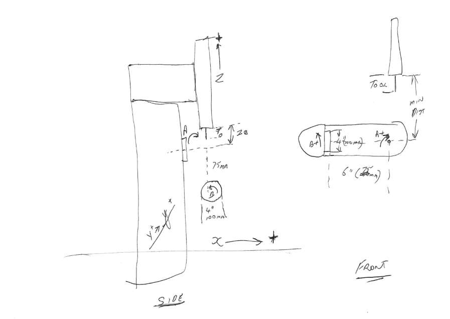
I'll keep plodding away
Grotius, I will look further at your work. I really want to keep it in bounds of linuxcnc
For the image in the opening post I would say :
WAT = WAB * BAA * AAP * PAT
(which is probably what you meant)
Yeh, this is what I meant.
A&B have to intersect
I did up a bit of a sketch of how I see the machine from the public specs (from the first post) Note 6" should be 3"
I'll keep plodding away
Attachments:
Last edit: 30 Nov 2022 19:36 by rodw.
Please Log in or Create an account to join the conversation.
Time to create page: 0.172 seconds