Deckel FP4 Gearbox Comp
- Walkahz
- Offline
- Junior Member
-

- Posts: 38
- Thank you received: 7
I am in the process of trying to get my Deckel FP4nc shifting gears.
I have ditched the standard motor control system of contactors and resistors and fitted a VFD that is configured to run at 50Hz as well as a jog at 5Hz to allow the gear shifting to take place.
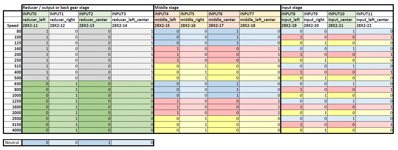
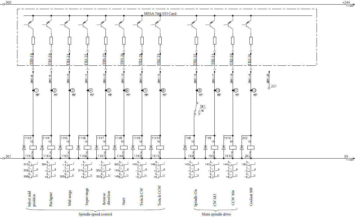
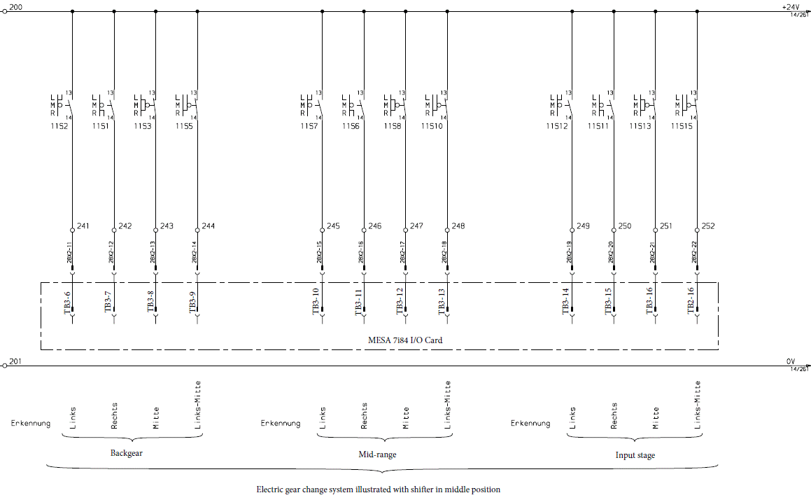
I have set up the gear motor relays the same as stock and there are 3 gear selector motors that are able to turn the selectors 360 deg.
Each selector has 3 microswitches to determine the position.
I have been looking into a few methods of setting up the gearbox comp including a modification of RotarySMP's MAHO component (i am struggling to get the halcompile to work correctly)
Or alternatively i have also found another user Niko provide his config in the following thread forum.linuxcnc.org/10-advanced-configura...-gearbox-comp#246671
Running the gearbox through classic ladder (which i am finding a little easier to follow and seems to be a perfect match for my machine)
To make this ladder based system work for my configuration i copied across the parts i thought were relevant from the hal file.
However once i had changed all the pin outs to suit my wiring i was unable to open linux CNC as it was throwing errors saying it was unable to find certain pins (i.e. the decode)
I tried opening the ladder program once i reset the hal as it comes straight out of PNCConfig but it seemed to be missing variables/pins as they were replaced with ???? (could be related the the hal??)
Apologies in advance for my lack of knowledge when it comes to hal and linux i am definately in over my head when it comes to code. I have attached my Hal and the ladder program for reference.
Regards
Josh
Please Log in or Create an account to join the conversation.
- Aciera
-

- Offline
- Administrator
-

- Posts: 4649
- Thank you received: 2070
That is because 'decode.' pins are created by a custom hal component called 'tumbler_decode'However once i had changed all the pin outs to suit my wiring i was unable to open linux CNC as it was throwing errors saying it was unable to find certain pins (i.e. the decode)
This is from the 'Deckel.hal' file in the post you linked:
loadrt tumbler_decode names=decode.0
addf decode.0            servo-thread
For this to work you will need to install the 'tumbler_decode.comp' from the original zip folder.
Please Log in or Create an account to join the conversation.
- Walkahz
- Offline
- Junior Member
-

- Posts: 38
- Thank you received: 7
Have checked it's included in the hal.
Please Log in or Create an account to join the conversation.
- Aciera
-

- Offline
- Administrator
-

- Posts: 4649
- Thank you received: 2070
loadrt tumbler_decode names=decode.0
addf decode.0 servo-thread
And you are still getting an error then I would comment out all the hal lines that contain 'decode.0' pins to get linuxcnc started and then use the 'show halconfiguration' tool to check that the 'decode.0' component is actually loaded and what pin have been created.
Please Log in or Create an account to join the conversation.
- Walkahz
- Offline
- Junior Member
-

- Posts: 38
- Thank you received: 7
Still no luck, everytime I comment something out a new reason to stop LCNC opening comes up in the error log. There must be something I am missing.
Going to change track for now and go back to the original plan of using a modification of rotarySMP's code.
one question I do have is how does the addressing system of pins work in external .comp files work?
The below is a snippet of the code. I'm assuming the 28X1... section is the reference for the pin or is it the whole "MESA 7i84 OUTPUT 0: 28X1-8"; line? How would I find the 28X1 address on my setup as i assume this will be different for everyone.
/* control pins */
pin out bit motor_lowspeed = 0 "MESA 7i84 OUTPUT 0: 28X1-8";
pin out bit reducer_motor = 0 "MESA 7i84 OUTPUT 1: 28X1-9";
pin out bit midrange_motor = 0 "MESA 7i84 OUTPUT 2: 28X1-10";
pin out bit input_stage_motor = 0 "MESA 7i84 OUTPUT 3: 28X1-11";
Please Log in or Create an account to join the conversation.
- Aciera
-

- Offline
- Administrator
-

- Posts: 4649
- Thank you received: 2070
The pin created here by this component will be '<componentname>.motor-lowspeed' and is preset to FALSE.pin out bit motor_lowspeed = 0 "MESA 7i84 OUTPUT 0: 28X1-8";
"MESA 7i84 OUTPUT 0: 28X1-8" is just a comment, presumably the output of the 7i84 used by the author in his particular setup. This has no impact on the pin name or location whatsoever.
Please Log in or Create an account to join the conversation.
- RotarySMP
-

- Offline
- Platinum Member
-

- Posts: 1542
- Thank you received: 572
Attachments:
Please Log in or Create an account to join the conversation.
- Walkahz
- Offline
- Junior Member
-

- Posts: 38
- Thank you received: 7
Short of me copying the pinout exactly I'm assuming that I will need to change this to suit my wiring.
Please Log in or Create an account to join the conversation.
- Aciera
-

- Offline
- Administrator
-

- Posts: 4649
- Thank you received: 2070
Please Log in or Create an account to join the conversation.
- Walkahz
- Offline
- Junior Member
-

- Posts: 38
- Thank you received: 7
Went back to review RotarySMP's wonderful Maho thread and 90% of the answers i needed were right there in his HAL file.
I am stuck on a couple of points though.
I have copied the 2 sections below out of Mark's HAL and done what i thought were the required modifications. The modified version of the code i found to suit the Deckel is half in german which is tough for a simple Aussie.
What files will these pins refer back to when opening linux CNC? at the moment unless i comment out like below it throws an error upon opening e.g. cant find pin FP4-gearbox.reducer-motor.
This will be due to a different naming syntax between the below and whatever file it references i would assume but i need to know what it is so i can modify correctly.
# --- GEARBOX CONTROL ---
#net sig_return_actual_speed FP4-gearbox.spindle-speed-out => motion.spindle-speed-in
#net sig_return_spindle-at-speed FP4-gearbox.spindle-at-speed => motion.spindle-at-speed
#net sig_stop_spindle FP4-gearbox.stop-spindle => motion.spindle-on
#net set-gear-shift-start FP4-gearbox.start-gear-shift => hm2_5i25.0.7i84.0.2.output-05
#net activate-vorgelege_motor FP4-gearbox.reducer-motor => hm2_7i96s.0.7i84.0.0.output-00
#net activate-block2_motor FP4-gearbox.midrange-motor => hm2_7i96s.0.7i84.0.0.output-01
#net set-shaft-motor-lowspeed FP4-gearbox.motor-lowspeed => hm2_7i96s.0.7i84.0.0.output-03
#net activate-block1_motor FP4-gearbox.input-stage-motor => hm2_7i96s.0.7i84.0.0.output-02
net activate-spindle-twitch-cw FP4-gearbox.twitch-cw => hm2_7i96s.0.7i84.0.0.output-04
net activate-spindle-twitch-ccw FP4-gearbox.twitch-ccw => hm2_7i96s.0.7i84.0.0.output-05
# --- GEARBOX CONTROL ---
#net sig_get_commanded_speed FP4-gearbox.spindle-speed-in-abs <= motion.spindle-speed-out-abs
#net sig_spindle_status FP4-gearbox.spindle-stopped <= hm2_5i25.0.7i84.0.2.input-19
#net sig_vorgelege_vorne FP4-gearbox.reducer-front <= hm2_7i96s.0.inm.00.input-02
#net sig_vorgelege_mitte FP4-gearbox.reducer-center <= hm2_7i96s.0.inm.00.input-03
#net sig_vorgelege_hinten FP4-gearbox.reducer-back <= hm2_7i96s.0.inm.00.input-04
#net sig_block2_vorne FP4-gearbox.middle-front <= hm2_7i96s.0.inm.00.input-05
#net sig_block2_mitte FP4-gearbox.middle-center <= hm2_7i96s.0.inm.00.input-06
#net sig_block2_hinten FP4-gearbox.middle-back <= hm2_7i96s.0.inm.00.input-07
#net sig_block1_vorne FP4-gearbox.input-front <= hm2_7i96s.0.inm.00.input-08
#net sig_block1_mitte FP4-gearbox.input-center <= hm2_7i96s.0.inm.00.input-09
#net sig_block1_hinten FP4-gearbox.input-back <= hm2_7i96s.0.inm.00.input-10
Thanks for being patient with me.
Please Log in or Create an account to join the conversation.


