
Help with Modbus needed
- viesturs.lacis
- Offline
- Premium Member
-

Less
More
- Posts: 114
- Thank you received: 3
03 Oct 2026 20:25 #350086
by viesturs.lacis
Help with Modbus needed was created by viesturs.lacis
Hello!
I need to control Invertek Optidrive E3 VFD from LinuxCNC. I have start/stop signal working from Mesa board output and I can set the speed from potentiometer but the actual user wants to set the speed from g-code to avoid potential mistakes, especially if there will be toolchange and different spindle speeds would be needed for different tools.
The thing is that all 4 analog outputs on Mesa 7i33 board are already used for servodrives, so I was thinking that I could hopefully set the frequency via modbus instead of getting new board just for analog output.
I have usb-to-rs485 converter, lsusb shows it as CH340 chip and I was able to determine that it is using ttyUSB0 port.
Here is the section of Optidrive E3 manual that describes the modbus message contents:
ibb.co/PzFsq8fP
And according to manual I can still have start/stop signal the way I have now even when the drive is in Modbus mode so what I would need is
to send the frequency value (optionally - read actual frequency to determine "spindle-at-speed" and "spindle-is-stopped"):
ibb.co/PGXK2gW5
I tried searching web of how to start and went for mb2hal route.
In HAL file I have:
loadusr -W mb2hal config=mb2hal.ini
Here is contents of mb2hal.ini file:
pastebin.com/h9qHcPR1
I tried looking at pins of mb2hal component in HalShow but the only thing that was changing was a pin that shows number of errors.
mb2hal.ini file has 2 entries about debug messages but I did not even understand where to find them so at the moment I have exactly no idea what is wrong and how to proceed so I would appreciate if someone could hold my hand and then gently poke in correct direction. It seems like a basic thing of what people are doing with VFDs over modbus but I have never done that.
Please Log in or Create an account to join the conversation.
- tommylight
-

- Away
- Moderator
-

Less
More
- Posts: 22001
- Thank you received: 7488
03 Oct 2026 21:27 #350087
by tommylight
Replied by tommylight on topic Help with Modbus needed
Please upload pictures and config files here on the forum, not on 3'rd party sites, they contain way to much bad scripts.
Please Log in or Create an account to join the conversation.
- rodw
-

- Offline
- Platinum Member
-

Less
More
- Posts: 12159
- Thank you received: 4150
04 Oct 2026 01:24 #350088
by rodw
Replied by rodw on topic Help with Modbus needed
Looks like register 2 sets the frequency. 7 is the actual frequency
at speed will use the near component to compare the two.
I did a detailed Youtube video showing how to use mb2hal recently. You will find it on my @MrRodW channel,
modbus lete you read concecutive registers in one call.
at speed will use the near component to compare the two.
I did a detailed Youtube video showing how to use mb2hal recently. You will find it on my @MrRodW channel,
modbus lete you read concecutive registers in one call.
The following user(s) said Thank You: viesturs.lacis
Please Log in or Create an account to join the conversation.
- viesturs.lacis
- Offline
- Premium Member
-
Less
More
- Posts: 114
- Thank you received: 3
04 Oct 2026 19:59 - 04 Oct 2026 20:01 #350109
by viesturs.lacis
Replied by viesturs.lacis on topic Help with Modbus needed
Rod, awesome video! I actually understood a lot more of that sample INI file, definitely had mistakes. hopefully now it is better (but seems like not yet good because it is not working completely).
I have attached:
1) mb2hal.hal file, which at the moment only loads mb2hal module
2) mb2hal.ini file
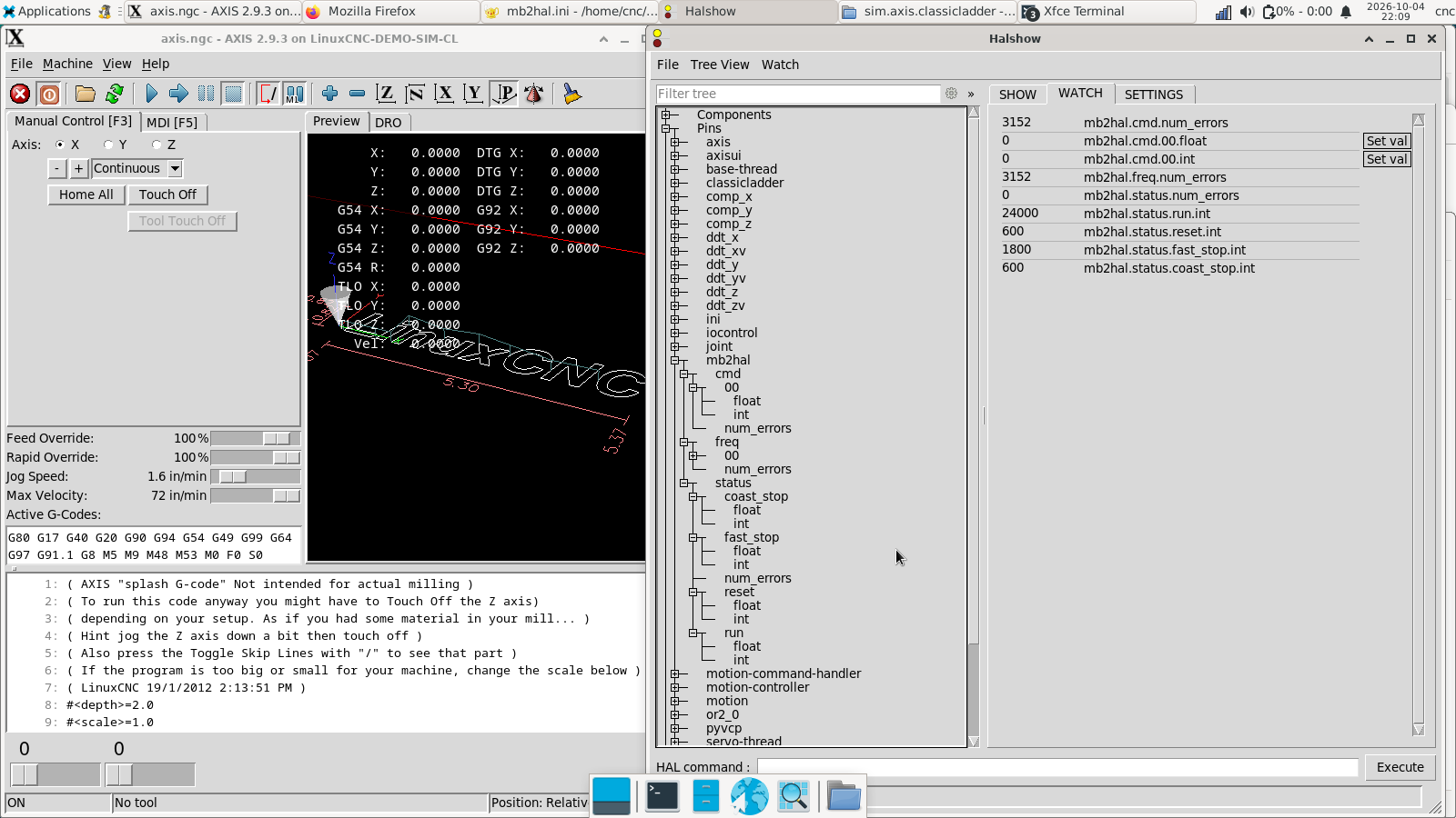
3) modbus.png which shows few hal pins of the mb2hal module. what I find a good sign there is that first transaction for reading the registers seem good, no errors are accumulated there
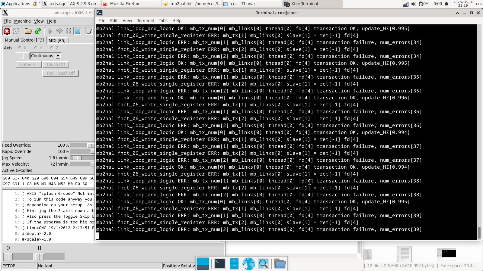
4) modbus error.png shows the error message in terminal when I started LinuxCNC there, maybe that is helpful for understanding what am I missing
5) VFD manual
6) VFD modbus register map
I have a suspicion that "First element" in mb2hal.ini is not correct because of the values that are reported on hal pins.Values of those hal pins match following settings from VFD: P-01 (max speed) is set to 24000 and P-02 (min speed) is set to 1800 and P-03 accel ramp time and P-04 decel ramp are both 6.0 seconds
And now as I was writing this, I checked - if I change P-04 parameter (decel time) to 7.0 seconds, mb2hal.status.coast_stop.int immediately changes value to 700 and changing P-03 to 5.6 seconds changes mb2hal.status.reset.int to 560 - hooray I have some basic communication going!
I chose those names according to functions of first 4 bits of register 1 that show status of VFD - I thought that they would reflect values of the first 4 bits, but now I see that they are integer type hal pins, so now I am confused which registers am I looking at.
I took the "First element" value of 128 from very bottom of page 36 of VFD manual (section 8.4 "Modbus register map")
Could you please hint me what am I doing wrong? Because from that register map I understand that register 4 holds accel / decel (from modbus register map it seems that it is one value used for both accel and decel but I proved that those are 2 separate values received from VFD) and I am somehow reading that but I do not see in that map any register that shows min and max speed settings. Where do those come from (got curious and checked - hal pin values are updated immediately when I change those settings in VFD)?
And it seems obvious that if the first transaction is not reading the register that I thought it would then other 2 transactions will not write the register that I thought they would and they produce those errors...
Thanks in advance!
Last edit: 04 Oct 2026 20:01 by viesturs.lacis.
Please Log in or Create an account to join the conversation.
- rodw
-
- Offline
- Platinum Member
-
Less
More
- Posts: 12159
- Thank you received: 4150
04 Oct 2026 21:46 #350112
by rodw
Replied by rodw on topic Help with Modbus needed
The error messages indicate that transaction 1 & 2 are bad but in reality all are bad.
the first register is a single 16 bit register. I would map functions to decimals. looks like it will become 0=off, 1= on
0 000 stop
1 001 run enable
2 010
3 011
4 100 coast stop
You don't have any hal plumbing.
You need to scale the desired speed to be a frequency in hal so S12000 should resolve to 200 Hz (2000 in register) - assuming normal 400 Hz VFD
Please Log in or Create an account to join the conversation.
- viesturs.lacis
- Offline
- Premium Member
-
Less
More
- Posts: 114
- Thank you received: 3
06 Oct 2026 15:28 - 06 Oct 2026 15:30 #350144
by viesturs.lacis
Replied by viesturs.lacis on topic Help with Modbus needed
yes, hal pins need to be connected but reading/sending values over modbus come before that. got that working and then also hal pins went quickly and easy
just a little detail in case somebody else will encounter this in the future:
Correct value of "First element" for first register is 0, thanks to Ralph Stirling for sharing a working config.
Attached is working ini and hal files for mb2hal and Invertek Optidrive E3
just a little detail in case somebody else will encounter this in the future:
Correct value of "First element" for first register is 0, thanks to Ralph Stirling for sharing a working config.
Attached is working ini and hal files for mb2hal and Invertek Optidrive E3
Last edit: 06 Oct 2026 15:30 by viesturs.lacis.
Please Log in or Create an account to join the conversation.
Time to create page: 0.143 seconds