retrofit Bridgeport Prototrak Plus
- new2linux
- Offline
- Platinum Member
-

Less
More
- Posts: 711
- Thank you received: 9
22 Jun 2016 17:35 #76453
by new2linux
Replied by new2linux on topic retrofit Bridgeport Prototrak Plus
Andy, There are 2 of them, the other is to the left of the one that blown, on the end of the blue capacitor. See the bottom pic of the last group of pics.
Please Log in or Create an account to join the conversation.
- Todd Zuercher
-

- Away
- Platinum Member
-
Less
More
- Posts: 4757
- Thank you received: 1459
22 Jun 2016 17:37 #76454
by Todd Zuercher
Replied by Todd Zuercher on topic retrofit Bridgeport Prototrak Plus
In your very first post to this thread, you have pictures of the amp and transformer still in the old box.
In the 2nd picture you can see the wiring from the transformer to the bridge rectifier.
You do not have the transformer wired the same as it was before (you now have wire 3 on terminal 2, wire 2 on terminal 1 and wire 1 on terminal 3.)
In the 2nd picture you can see the wiring from the transformer to the bridge rectifier.
You do not have the transformer wired the same as it was before (you now have wire 3 on terminal 2, wire 2 on terminal 1 and wire 1 on terminal 3.)
The following user(s) said Thank You: new2linux
Please Log in or Create an account to join the conversation.
- new2linux
- Offline
- Platinum Member
-
Less
More
- Posts: 711
- Thank you received: 9
22 Jun 2016 18:28 #76456
by new2linux
Replied by new2linux on topic retrofit Bridgeport Prototrak Plus
I have just seen that. And you are so right. Do you think that a resister is all I will need?
Please Log in or Create an account to join the conversation.
- Muzzer
- Offline
- Elite Member
-

Less
More
- Posts: 266
- Thank you received: 42
22 Jun 2016 20:01 #76459
by Muzzer
Replied by Muzzer on topic retrofit Bridgeport Prototrak Plus
The blown resistor seems to be in series with the small blue electrolytic cap, so it's possibly forming a simple RC filter. Most likely explanation for over stressing it would be a short circuit across the small blue cap (your external wiring?). I assume the bottom of both caps is local 0V ie the main copper island.
Try measuring the resistance across the small blue cap. After a second or two to charge it up, the meter should read high resistance unless you have a short and depending what is connected to it. What connects across the small blue cap?
Also worth checking you have correctly connected up that diode bridge I can see on the bench top. If you have misconnected it and are trying to charge the caps up reverse voltage or with an AC voltage, one or both caps would break down. That can be messy and "alarming", although most modern caps have a sacrificial vent to prevent dangerous explosions.
The following user(s) said Thank You: new2linux
Please Log in or Create an account to join the conversation.
- Todd Zuercher
-
- Away
- Platinum Member
-
Less
More
- Posts: 4757
- Thank you received: 1459
22 Jun 2016 20:38 #76463
by Todd Zuercher
Replied by Todd Zuercher on topic retrofit Bridgeport Prototrak Plus
From the looks of the pictures, There are (or were) two rectifiers, a little one that was fed 5v AC (the visible one mounted to the bottom edge of the box), and a big one that was fed 26v AC (hiding on the back side of the PCB beside the big blue cap and heat-sinked to a plate or some big piece of metal.)
He connected 26v AC to the 0v input
the 0v to the 5v AC input
the 5v AC to the 26v AC input
I'm afraid the likely hood of there being significant damage to both x and y amps is pretty high.
He connected 26v AC to the 0v input
the 0v to the 5v AC input
the 5v AC to the 26v AC input
I'm afraid the likely hood of there being significant damage to both x and y amps is pretty high.
The following user(s) said Thank You: new2linux
Please Log in or Create an account to join the conversation.
- new2linux
- Offline
- Platinum Member
-
Less
More
- Posts: 711
- Thank you received: 9
22 Jun 2016 20:55 - 23 Jun 2016 11:55 #76465
by new2linux
Replied by new2linux on topic retrofit Bridgeport Prototrak Plus
Thanks Muzzer, very glad to here from you! With the ohm meter set on Rx1 it will read just below 1/2 of the scale (26 ohms); wait a few seconds, reverse meter probes and the meter will go full scale then slowly settle down to just a small amount off the low end (the left side) of scale, around 300 ohms. The measurement was at the 2 terminals (the one has a + beside it) where it says C3, on the PCB.
When you talk of 2 capacitors I think the 2nd one is the small ( 1/2 dia) darker blue (has blue film around the outside) cylinder with cross on the end towards the camera is the 2nd capacitor.
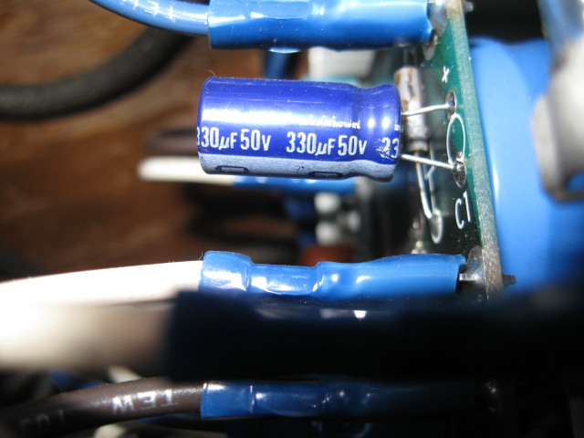
This is the 2nd cap
Not really shore what to call it.
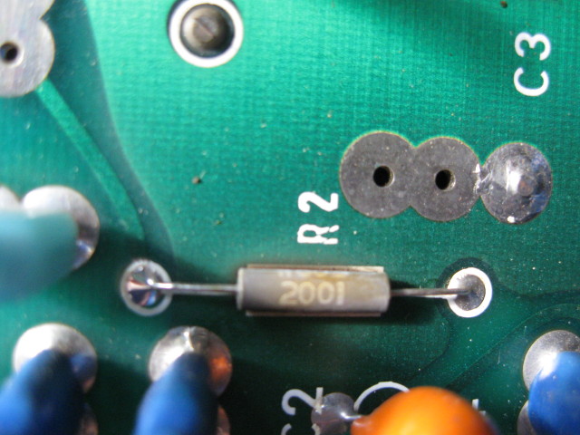
Resistor says 2001; FRJ; and W80S (2001 the yr of manufacture)
Do you think all these require replacement?
I have tried the 1 1/2 v battery on both "x" & "y" without success.
Edit: I offer my apologize to all on the form for my own doings, and especially the ones (they know who they are) who I may have worn out my welcome with. Each of you have been overly generous with your time, knowledge and kindness.
Many thanks
When you talk of 2 capacitors I think the 2nd one is the small ( 1/2 dia) darker blue (has blue film around the outside) cylinder with cross on the end towards the camera is the 2nd capacitor.
This is the 2nd cap
Not really shore what to call it.
Resistor says 2001; FRJ; and W80S (2001 the yr of manufacture)
Do you think all these require replacement?
I have tried the 1 1/2 v battery on both "x" & "y" without success.
Edit: I offer my apologize to all on the form for my own doings, and especially the ones (they know who they are) who I may have worn out my welcome with. Each of you have been overly generous with your time, knowledge and kindness.
Many thanks
Last edit: 23 Jun 2016 11:55 by new2linux. Reason: To offer thanks
Please Log in or Create an account to join the conversation.
- Muzzer
- Offline
- Elite Member
-
Less
More
- Posts: 266
- Thank you received: 42
22 Jun 2016 21:38 #76466
by Muzzer
Hard to say what might have failed first and whether the resistor saved the downstream circuits. Ideally you'd power up the X and Y 5V circuits one at a time with a nice bench PSU so you can limit the current draw - or failing that, a USB or 5V wall wart supply. If that looks hopeful and the 5V rail stays up, you could then connect up the higher voltage rectifier and see if it still works.
Have you got a schematic diagram for the servo amps? Looks as if there is a 5V digital circuit and a higher voltage power circuit. I doubt you will have damaged the power circuit. If you can post the schematic I could have a look at it if you can't stir any life into it.
Replied by Muzzer on topic retrofit Bridgeport Prototrak Plus
Sounds as if the little purple / blue cap may be the smoothing cap for the unregulated 5V rail. It should see something like 7- 8Vdc after the bridge and presumably has a linear regulator between it and the 5V control circuit. If the 26V winding has been connected to it, it may have seen the best part of 40Vdc - depends what "26V" means - is that the rectified DC voltage or the secondary AC voltage on the transformer etc. A traditional old linear regulator like LM7805 is only rated to 35Vdc input. It's possible that may have popped but no telling if any further damage resulted.He connected 26v AC to the 0v input
the 0v to the 5v AC input
the 5v AC to the 26v AC input
I'm afraid the likely hood of there being significant damage to both x and y amps is pretty high.
Hard to say what might have failed first and whether the resistor saved the downstream circuits. Ideally you'd power up the X and Y 5V circuits one at a time with a nice bench PSU so you can limit the current draw - or failing that, a USB or 5V wall wart supply. If that looks hopeful and the 5V rail stays up, you could then connect up the higher voltage rectifier and see if it still works.
Have you got a schematic diagram for the servo amps? Looks as if there is a 5V digital circuit and a higher voltage power circuit. I doubt you will have damaged the power circuit. If you can post the schematic I could have a look at it if you can't stir any life into it.
The following user(s) said Thank You: new2linux
Please Log in or Create an account to join the conversation.
- Muzzer
- Offline
- Elite Member
-
Less
More
- Posts: 266
- Thank you received: 42
23 Jun 2016 12:44 #76487
by Muzzer
Replied by Muzzer on topic retrofit Bridgeport Prototrak Plus
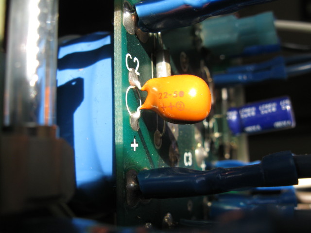
The little yellow cap is a tantalum chip (22uF 5V?). If that had failed, it would have gone short circuit. Similarly, the 330uF 50V is probably OK, as it would have vented if it failed. You'd see the end of the can opened up and sticky liquid escaped.
Date codes on products of this age are usually in the form "9735" which would be week 35 of 1997 in that example. But there is no fixed convention so the 2001 could indeed be the date or possibly the value ("2001" = 200 x 101 = 2k Ohm in resistor speak).
Are there any other components on the other side of the board? Something is limiting the voltage on the tantalum cap to 5V, such as a zener diode. If you trace the tracks from the +ve of the 330uF cap, does it connect through a resistor to the tatalum cap?
Very difficult to see what is going on in these partial snapshots. Could you get some better views of the board showing the all tracks in one view and check for compts on the other side?
You'd need to apply the full 5V to power up the controls (eg across the tantalum cap), assuming it really is a 5V rail. 1.5V won't wake up processors and logic circuits.
The following user(s) said Thank You: new2linux
Please Log in or Create an account to join the conversation.
- andypugh
-

- Offline
- Moderator
-

Less
More
- Posts: 19875
- Thank you received: 4642
23 Jun 2016 13:10 #76488
by andypugh
As mentioned earlier, this should be from a current-limited supply.
Your 1.5V battery is low voltage but _not_ lo current. I would go as far as to suggest buying a lab power supply (variable voltage, variable current), if you intend to carry on playing this game, and especially if you are going to carry on blowing things up, they are useful things to have. Pro-rata the cost through all the years you will have it for.
I don't know where you live so don't know what high-steet shops you have. In the UK we have
www.maplin.co.uk/p/100w-slim-bench-power-supply-n93cx
Radios Shack in the US seem to be useless now, but Amazon have
www.amazon.com/Lavolta-BPS305-Variable-L...s=bench+power+supply
Replied by andypugh on topic retrofit Bridgeport Prototrak Plus
You'd need to apply the full 5V to power up the controls (eg across the tantalum cap), assuming it really is a 5V rail
As mentioned earlier, this should be from a current-limited supply.
Your 1.5V battery is low voltage but _not_ lo current. I would go as far as to suggest buying a lab power supply (variable voltage, variable current), if you intend to carry on playing this game, and especially if you are going to carry on blowing things up, they are useful things to have. Pro-rata the cost through all the years you will have it for.
I don't know where you live so don't know what high-steet shops you have. In the UK we have
www.maplin.co.uk/p/100w-slim-bench-power-supply-n93cx
Radios Shack in the US seem to be useless now, but Amazon have
www.amazon.com/Lavolta-BPS305-Variable-L...s=bench+power+supply
The following user(s) said Thank You: new2linux
Please Log in or Create an account to join the conversation.
- new2linux
- Offline
- Platinum Member
-
Less
More
- Posts: 711
- Thank you received: 9
23 Jun 2016 13:19 - 23 Jun 2016 13:55 #76489
by new2linux
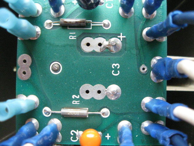
will this pic work
Earlier when I was trying to understand how it operated, I got the drive to move by applying low voltage I believe I started with 1 1/2 v and went to 3 v dc.
Edit: Andy, Thanks for your help.
Edit: Muzzer, the Resistor says 2001; FRJ; and W80S , I have contacted Mouser with the info I have, and the pic you see.
Replied by new2linux on topic retrofit Bridgeport Prototrak Plus
will this pic work
Earlier when I was trying to understand how it operated, I got the drive to move by applying low voltage I believe I started with 1 1/2 v and went to 3 v dc.
Edit: Andy, Thanks for your help.
Edit: Muzzer, the Resistor says 2001; FRJ; and W80S , I have contacted Mouser with the info I have, and the pic you see.
Last edit: 23 Jun 2016 13:55 by new2linux.
Please Log in or Create an account to join the conversation.
Moderators: piasdom
Time to create page: 0.398 seconds