Retrofitting a 1986 Maho 400E
- akb1212
- Offline
- Senior Member
-

Less
More
- Posts: 74
- Thank you received: 12
01 Oct 2018 12:39 #118285
by akb1212
Replied by akb1212 on topic Retrofitting a 1986 Maho MH400E
Loddestuen and all,
I hope you end up buying this mill! And you seem to be in good shape to do this, with the background to get all the difficult practical things fixed.
The software part is possible to learn, and as you must have seen by now the support here is absolutely comparable to other commercial vendors! Absolutely top notch!
I have a Maho MH600E from 1990 I'm restoring, so I do know that it's quite a bit of work to undertake. But at the same time it's highly rewarding when you succeed.
My mill isn't fully running yet, that is the conversion isn't fully completed. And there have been a long period of no time to spend on this project. But I hope to be able to get something done on this soon.
And if you haven't seen it yet I suggest you visit the thread I started about it on Practical Machinist: www.practicalmachinist.com/vb/dmg-mori-g...-maho-thread-270525/
It's long, but should be a good starting point if you haven't already seen it.
I expect this mill comes with a tool changer? I think that was standard on the -C class of Mahos? In that case I'd be really interested in participating it getting this sorted, as this is one of the missing prices on my retrofit.
An important point with the machine you are considering is the available documentation. That will be of huge help, and make everything go a lot smoother.
Hope to see you here soon with a new retrofit project!
Regards
Anders from Norway
Please Log in or Create an account to join the conversation.
- RotarySMP
-
 Topic Author
- Offline
- Platinum Member
-

Less
More
- Posts: 1518
- Thank you received: 560
02 Oct 2018 08:20 #118334
by RotarySMP
Replied by RotarySMP on topic Retrofitting a 1986 Maho MH400E
Bob,
I took a look at that X axis braided conduit yesterday, but there is no obvious brand marking on it. The mounting hardware is marked PG 29 TYP US ... .
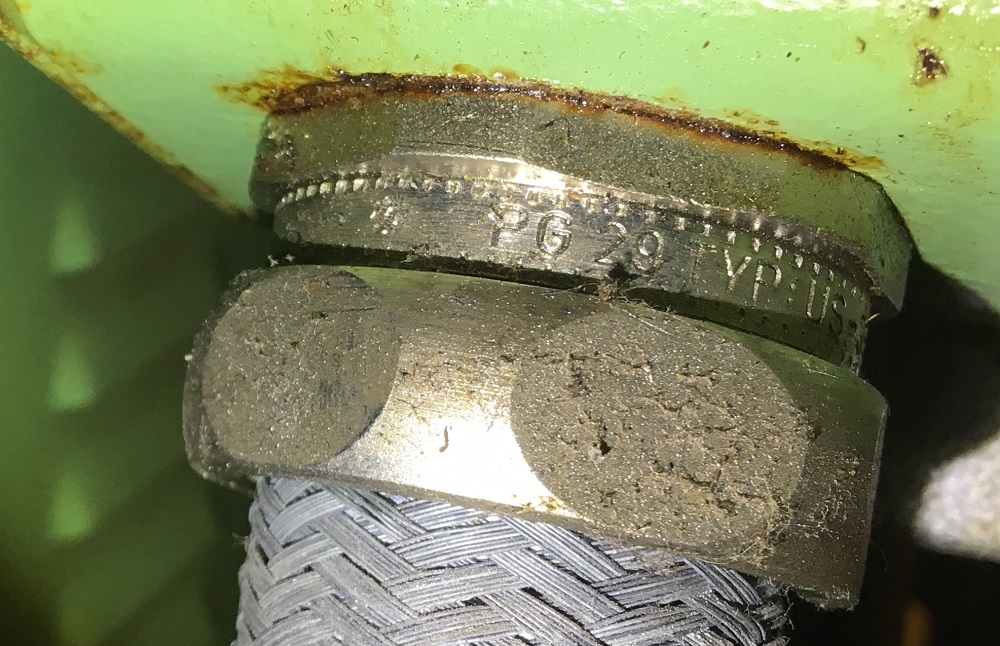
Sorry, I just realised I didn't get a full shot of that part number, but googling it reveals that PG29 is just a generic gland nut.
www.mencom.com/shop/cable-glands/pg29-me...ass-0-702-0-994.html
The Z axis conduit is larger. Sorry I forgot to photograph that as well.
Jesper,
I would agree with Christian that the best thing would be to get it up and running with the Phillips first. I'd contact DMG and ask them nicely for the constants. Starting a retrofit with a non-functional machine leaves you scratching your head whether things are not working because you made a mistake, or because there is an unidentified existing failure.
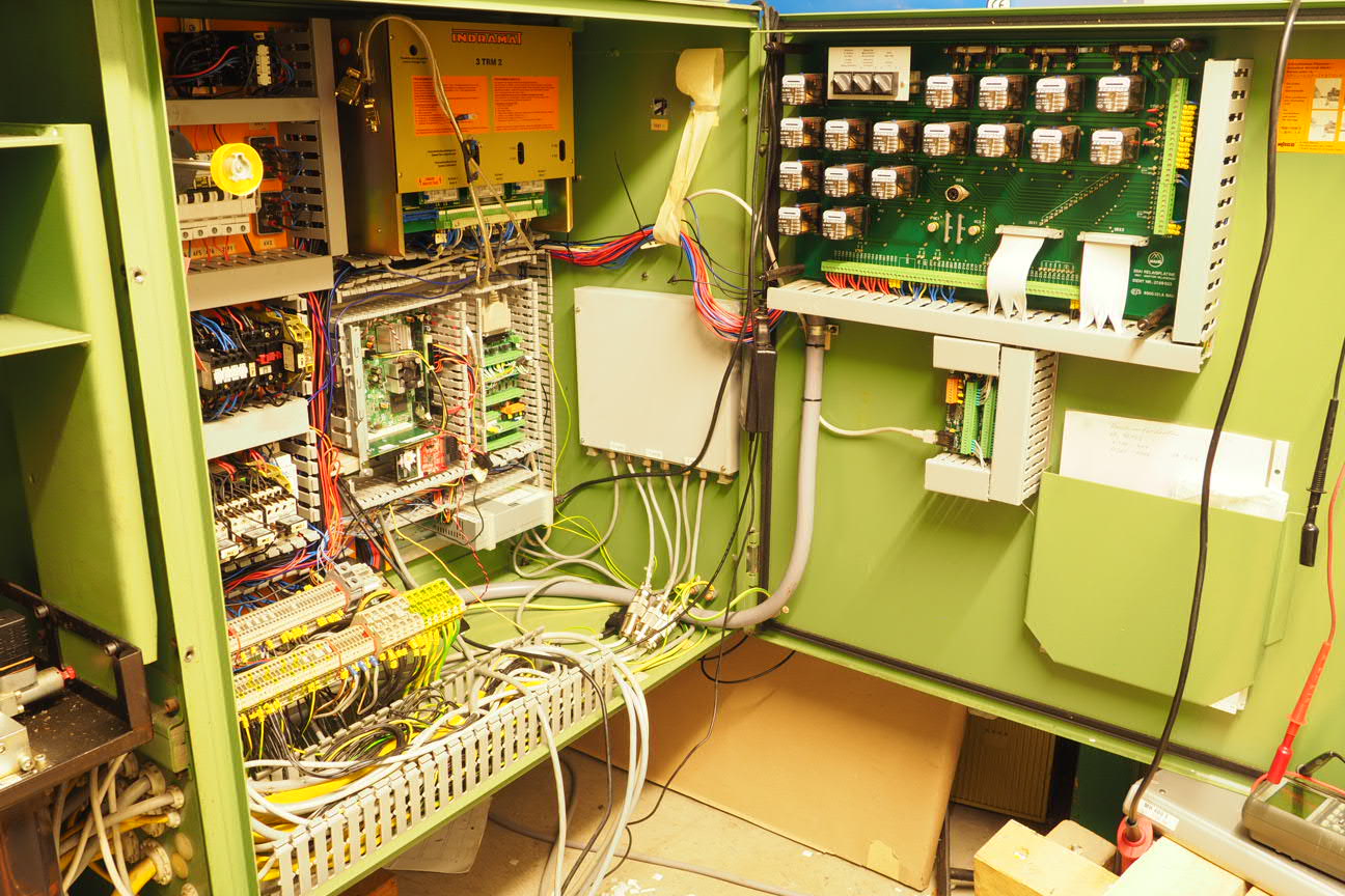
You will need to get more information, such as photos of the control cabinet. In google I found these photos of the 700C...
www.aptint.com/en/used-second-hand-machi...0-y-500-z-400mm_9317
Here are some ideas, based on what I see there...
- You have schematics, that is good (essential). Whether you retrofit of not, owning one of these machines without schematics would be a nightmare.
- There appears to be a control relay panel at the bottom of the control cabinet. This is not the same as the 28A1 used on the MHx00E series, but appears more simple.
- Since the spindle is driven by a huge DC motor, how is your power service? I am running my MH400E off a household 16A 400VAC 3PH supply, and occasionally the inrush trips the breaker when I first power up the machine. I haven't had any cutting loads yet, so this may be an issue. The 700C will need a much higher current supply.
- MuellerNick retrofitted a 700C years ago. They only have a single gearbox control stage, so you could probably adapt the gearbox.comp Andy Pugh wrote for his Holbrook, or adapt the comp Sergey wrote for me. To start with you could probably do manual gear changes, as the DC spindle speed control should cover many jobs.
www.youtube.com/user/MuellerNick/videos
- The 700C has three Indramats, a 1TRM3, a 3TRM2 and a third one which I can't read. I am going to assume that the 3TRM2 drives the three X/Y/Z axis. This is the same unit which the MHx00E series used. I would guess that the 1TRM3 controls the main spindle DC motor. I'd also guess that that the third indramat controls the four axis and the tool changer drive. Indramats are easy to control with the MESA 7i77, which can control up to six axis. If the drives and motors still work, this is the easiest part of the retrofit, as you only connect two wires per axis.
- MuellerNicks 700C had Phillips linear encoders, which he analysed the output of, but couldn't reverse engineer the signal for. He replaced them with modern TLL output encoders. If the encoder mounts are anything like on my Maho, it is a simple job to replace them. TLL encoders can be read directly by the MESA7i77. If I can't get my two flakey encoders working reliably, I will also be replacing them.
- The LinuxCNC side of things is not that complicated. Takes a while to get your head around the HAL and INI syntax, but I am also no programmer, but with the generous assistance of the forum, have been able to solve each challenge so far.
As Anders said, go for it. The cool thing about a MAHO is the modular control design. You can break it down into steps, and get things going piece by piece.
- get a PC running on the live image of LinuxCNC
- get the Mesa cards installed and running
- Install the PC in the control cabinet
- get the hardware E-Stop chain connected to LinuxCNC
- connect the I/O to the MESA's
- connect in the linear encoders and get postion feedback
- connect up the Indramats and get closed loop motion
- configure your HAL and INI
- modify a COMP to bring your spindle gearbox under LinuxCNC control.
- make a user control module
- make a pendant.
I can understand how someone with more experience, drive and motivation than me could retrofit one of these machines in about a month of evenings. Mine is taking much longer because:
- Laziness
- other projects
- steep learning curve for me
- making a new control cabinet from scratch, which is not really necessary.
- paralysis by analysis.
Mark
I took a look at that X axis braided conduit yesterday, but there is no obvious brand marking on it. The mounting hardware is marked PG 29 TYP US ... .
Sorry, I just realised I didn't get a full shot of that part number, but googling it reveals that PG29 is just a generic gland nut.
www.mencom.com/shop/cable-glands/pg29-me...ass-0-702-0-994.html
The Z axis conduit is larger. Sorry I forgot to photograph that as well.
Jesper,
I would agree with Christian that the best thing would be to get it up and running with the Phillips first. I'd contact DMG and ask them nicely for the constants. Starting a retrofit with a non-functional machine leaves you scratching your head whether things are not working because you made a mistake, or because there is an unidentified existing failure.
You will need to get more information, such as photos of the control cabinet. In google I found these photos of the 700C...
www.aptint.com/en/used-second-hand-machi...0-y-500-z-400mm_9317
Here are some ideas, based on what I see there...
- You have schematics, that is good (essential). Whether you retrofit of not, owning one of these machines without schematics would be a nightmare.
- There appears to be a control relay panel at the bottom of the control cabinet. This is not the same as the 28A1 used on the MHx00E series, but appears more simple.
- Since the spindle is driven by a huge DC motor, how is your power service? I am running my MH400E off a household 16A 400VAC 3PH supply, and occasionally the inrush trips the breaker when I first power up the machine. I haven't had any cutting loads yet, so this may be an issue. The 700C will need a much higher current supply.
- MuellerNick retrofitted a 700C years ago. They only have a single gearbox control stage, so you could probably adapt the gearbox.comp Andy Pugh wrote for his Holbrook, or adapt the comp Sergey wrote for me. To start with you could probably do manual gear changes, as the DC spindle speed control should cover many jobs.
www.youtube.com/user/MuellerNick/videos
- The 700C has three Indramats, a 1TRM3, a 3TRM2 and a third one which I can't read. I am going to assume that the 3TRM2 drives the three X/Y/Z axis. This is the same unit which the MHx00E series used. I would guess that the 1TRM3 controls the main spindle DC motor. I'd also guess that that the third indramat controls the four axis and the tool changer drive. Indramats are easy to control with the MESA 7i77, which can control up to six axis. If the drives and motors still work, this is the easiest part of the retrofit, as you only connect two wires per axis.
- MuellerNicks 700C had Phillips linear encoders, which he analysed the output of, but couldn't reverse engineer the signal for. He replaced them with modern TLL output encoders. If the encoder mounts are anything like on my Maho, it is a simple job to replace them. TLL encoders can be read directly by the MESA7i77. If I can't get my two flakey encoders working reliably, I will also be replacing them.
- The LinuxCNC side of things is not that complicated. Takes a while to get your head around the HAL and INI syntax, but I am also no programmer, but with the generous assistance of the forum, have been able to solve each challenge so far.
As Anders said, go for it. The cool thing about a MAHO is the modular control design. You can break it down into steps, and get things going piece by piece.
- get a PC running on the live image of LinuxCNC
- get the Mesa cards installed and running
- Install the PC in the control cabinet
- get the hardware E-Stop chain connected to LinuxCNC
- connect the I/O to the MESA's
- connect in the linear encoders and get postion feedback
- connect up the Indramats and get closed loop motion
- configure your HAL and INI
- modify a COMP to bring your spindle gearbox under LinuxCNC control.
- make a user control module
- make a pendant.
I can understand how someone with more experience, drive and motivation than me could retrofit one of these machines in about a month of evenings. Mine is taking much longer because:
- Laziness
- other projects
- steep learning curve for me
- making a new control cabinet from scratch, which is not really necessary.
- paralysis by analysis.
Mark
The following user(s) said Thank You: Bernd
Please Log in or Create an account to join the conversation.
- RotarySMP
-
Topic Author
- Offline
- Platinum Member
-
Less
More
- Posts: 1518
- Thank you received: 560
02 Oct 2018 08:26 - 02 Oct 2018 08:32 #118335
by RotarySMP
Replied by RotarySMP on topic Retrofitting a 1986 Maho MH400E
Christian,
Yes my MH400E has the Heidenhain LS-403's. The cable is hard wired to the sensor head with about five meter cable to an M23 connector. I recycled the three axis EXE board from the Phillips control cabinet.
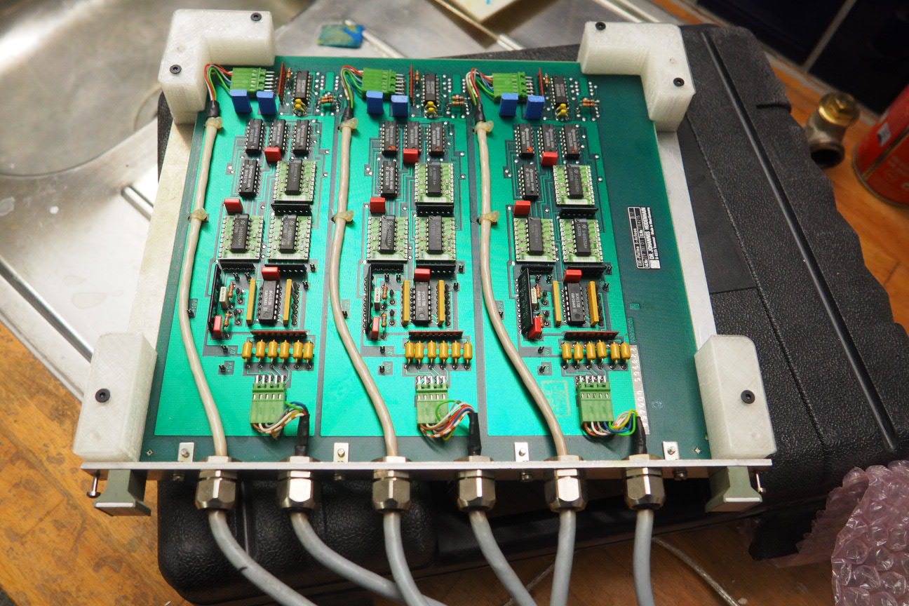
It is also hard wired with the matching connectors to the encoders, and with hard wired output cables to the Phillips. I made a metal shield (the grey square) for that EXE board and mounted it to the wall of the cabinet. You can see the encoder connectors on the floor of the control cabinet.
The only change I made was to cut off the Phillips dSub connectors, and terminate these wire into the MESA 7i77. Since the X axis encoder -> EXE -> Mesa signal path works perfectly, I have used that encoder to check the other two axis of the EXE, and they work.
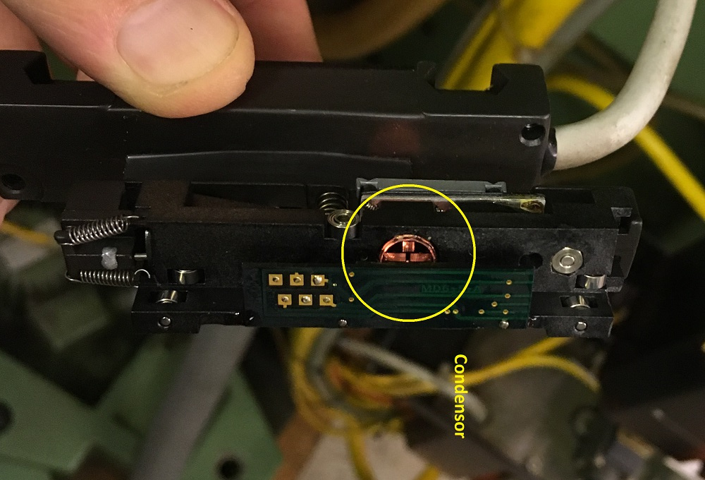
Yesterday I pulled the sensing head from the Y axis.
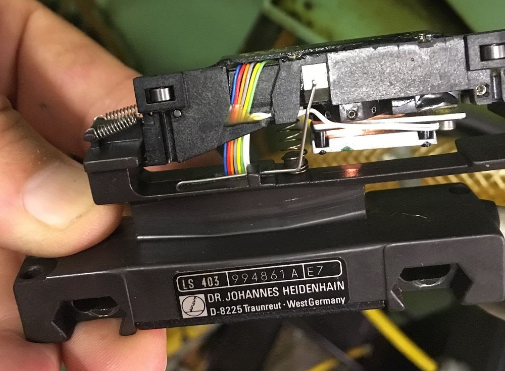
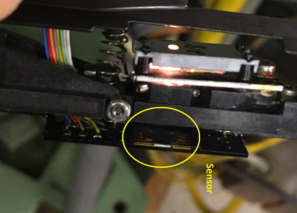
This is the axis which has a signal but is flakey. I cleaned the scale a few months ago and it started working normally, then got flakey again. As you can see it is not a bulb issue.
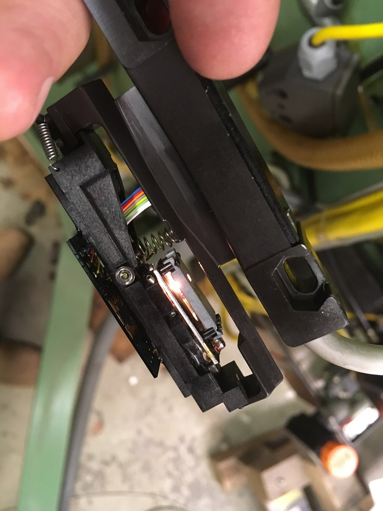
I'll reclean the scale, and this time also try to clean the condensor and sensor more thoroughly.
The solder joints of the wiring look fine.
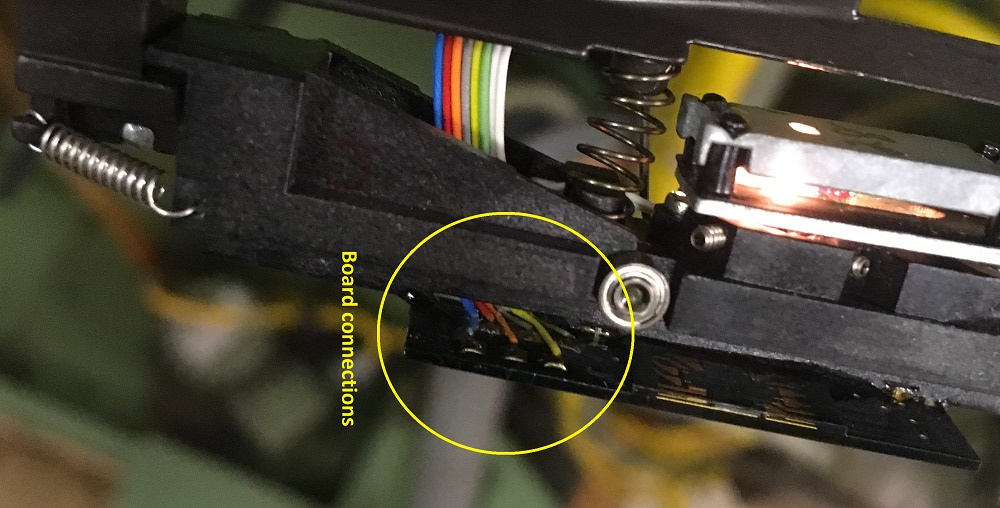
Good idea to look at cleaning the pins on the m23 connectors. They look spotless, but cleaning should remove a variable.
Mark
Yes my MH400E has the Heidenhain LS-403's. The cable is hard wired to the sensor head with about five meter cable to an M23 connector. I recycled the three axis EXE board from the Phillips control cabinet.
It is also hard wired with the matching connectors to the encoders, and with hard wired output cables to the Phillips. I made a metal shield (the grey square) for that EXE board and mounted it to the wall of the cabinet. You can see the encoder connectors on the floor of the control cabinet.
The only change I made was to cut off the Phillips dSub connectors, and terminate these wire into the MESA 7i77. Since the X axis encoder -> EXE -> Mesa signal path works perfectly, I have used that encoder to check the other two axis of the EXE, and they work.
Yesterday I pulled the sensing head from the Y axis.
This is the axis which has a signal but is flakey. I cleaned the scale a few months ago and it started working normally, then got flakey again. As you can see it is not a bulb issue.
I'll reclean the scale, and this time also try to clean the condensor and sensor more thoroughly.
The solder joints of the wiring look fine.
Good idea to look at cleaning the pins on the m23 connectors. They look spotless, but cleaning should remove a variable.
Mark
Last edit: 02 Oct 2018 08:32 by RotarySMP.
The following user(s) said Thank You: J Green
Please Log in or Create an account to join the conversation.
- andypugh
-

- Offline
- Moderator
-

Less
More
- Posts: 19731
- Thank you received: 4577
02 Oct 2018 09:04 #118337
by andypugh
PG = Panzergewinde = Stahlpanzerrohrgewinde = steel armoured conduit thread
en.wikipedia.org/wiki/Panzergewinde
It's an interesting thread in that it has an 80 degree thread angle, so has a relatively shallow depth for the pitch.
(I think the steepest full-thread is BA at 47.5 degrees. Proper threads are 55 degrees, of course")
Replied by andypugh on topic Retrofitting a 1986 Maho MH400E
Sorry, I just realised I didn't get a full shot of that part number, but googling it reveals that PG29 is just a generic gland nut.
PG = Panzergewinde = Stahlpanzerrohrgewinde = steel armoured conduit thread
en.wikipedia.org/wiki/Panzergewinde
It's an interesting thread in that it has an 80 degree thread angle, so has a relatively shallow depth for the pitch.
(I think the steepest full-thread is BA at 47.5 degrees. Proper threads are 55 degrees, of course
The following user(s) said Thank You: J Green
Please Log in or Create an account to join the conversation.
- Bernd
- Offline
- New Member
-

Less
More
- Posts: 11
- Thank you received: 2
02 Oct 2018 12:19 #118342
by Bernd
Replied by Bernd on topic Retrofitting a 1986 Maho MH400E
Hey y’all
your work and your colected know how in this forum is so professional, i thougt i could be able to do also a Retrofit.")
So i bought today a Maho 500C, with a problem on the control, i atached a picture with the screen,wich shows the error.
Im a mechanical engineer, and know CNC, CAM ec. but have no skils in Linux.
Maybe i can disturb you sometimes with my questions, and one more Maho gets a new life
greetings from Southtirol
Bernd
your work and your colected know how in this forum is so professional, i thougt i could be able to do also a Retrofit.
So i bought today a Maho 500C, with a problem on the control, i atached a picture with the screen,wich shows the error.
Im a mechanical engineer, and know CNC, CAM ec. but have no skils in Linux.
Maybe i can disturb you sometimes with my questions, and one more Maho gets a new life
greetings from Southtirol
Bernd
Please Log in or Create an account to join the conversation.
- gernoff
- Offline
- Senior Member
-
Less
More
- Posts: 43
- Thank you received: 2
02 Oct 2018 16:37 #118364
by gernoff
Replied by gernoff on topic Retrofitting a 1986 Maho MH400E
Mark;
As you can see your work on this project is inspiring others! Thank you. I will eventually be doing the same. I've just started a thread on converting my Deckel FP5NC and will try to include the levels of detail you have. My DC BBC driven spindle motor died and I am installing a VFD controlled motor in its place. Initially I hope to get it running with all my other existing hardware so it can handle shifting etc.
The work done here on the shifting .hal is going to help immensely during an actual LinuxCNC conversion.
In you spare time........ I am sure the group here would appreciate a synopsis of how you went about the reverse engineering of all the relay based logic chains these machines have. Sort of a 'getting started' guide. You could call it "Deckel / Maho LinuxCNC Conversion for Dummies"
The following user(s) said Thank You: RotarySMP
Please Log in or Create an account to join the conversation.
- cgroth
- Offline
- Junior Member
-

Less
More
- Posts: 28
- Thank you received: 9
02 Oct 2018 17:07 #118366
by cgroth
Replied by cgroth on topic Retrofitting a 1986 Maho MH400E
The 3TRM2 is the amplifier for X,Y,Z-axis (3 axis 2 pulse) driving permanent magnet DC motors with tacho generator. A 1TRM does the same for 1 axis and is usually built in when the machine has a 4th rotary axis. The DC spindle motor is driven by a TRK6 which is called 6 pulse controller capable to controll the rotor and field current thus enabling something like a constant torque drive. Christian
Please Log in or Create an account to join the conversation.
- cgroth
- Offline
- Junior Member
-
Less
More
- Posts: 28
- Thank you received: 9
02 Oct 2018 17:23 #118368
by cgroth
Replied by cgroth on topic Retrofitting a 1986 Maho MH400E
Mark, my scales are equipped with a remote m23 socket, connected by a 20cm cable. These connections where performed by Heidenhain and are a bit difficult to service. I expect the sensor head and the glass scale to be fine. If there had been a scratch or dirt on the scale, the failure would always occur at a distinct position. The Heidenhain EXE has a separate failure signal to indicate a missing edge or false differential signal. Maybe it is worth getting one and check the scale if you are sure the wiring is fine. The original 3x2 + 1x2 cable itself is quite robust, meaning as long as you can't see a mechanical damage it is electrically fine. Maybe you already wrote it but did you swap the scales of different axis (with the drives off!) to check the EXE? Christian
The following user(s) said Thank You: RotarySMP
Please Log in or Create an account to join the conversation.
- gernoff
- Offline
- Senior Member
-
Less
More
- Posts: 43
- Thank you received: 2
02 Oct 2018 18:16 #118369
by gernoff
Replied by gernoff on topic Retrofitting a 1986 Maho MH400E
Is the EXE boards interpolation level adjustable?
Please Log in or Create an account to join the conversation.
- cgroth
- Offline
- Junior Member
-
Less
More
- Posts: 28
- Thank you received: 9
03 Oct 2018 06:03 #118386
by cgroth
Replied by cgroth on topic Retrofitting a 1986 Maho MH400E
Bob,
you may get flexible sleeves here, though I did not try them yet:
www.techflex.org/de/verzinntes-kupfer-ge...t-tinned-copper.html
From the EMI point of view it is not necessary as long as you use good cable, which has separate shieldings per differential pair and / or shielded power cables. It is not that easy to push the cables throught the metal slevees yet they give your machine a decent touch. Christian
The following user(s) said Thank You: J Green
Please Log in or Create an account to join the conversation.
Moderators: piasdom
Time to create page: 0.356 seconds