
- Posts: 19899
- Thank you received: 4655
Retrofitting a 1986 Maho MH400E
- andypugh
- Offline
- Moderator
-

Less
More
7 years 5 months ago - 7 years 5 months ago #134202
by andypugh
He was talking about pulling the B18 (Jacobs taper) out, so I think that was the plan.
Talking about Jacobs Tapers, the hugest one (JT5) isn't much use for anything, but the shanks with it can be cheaper than dedicated soft-arbors.
Replied by andypugh on topic Retrofitting a 1986 Maho MH400E
Mike_Eitel wrote: Hi RotarySMP
I own a tapmatic. You can exchange the shank. That way it will not get even longer than it is already.
He was talking about pulling the B18 (Jacobs taper) out, so I think that was the plan.
Talking about Jacobs Tapers, the hugest one (JT5) isn't much use for anything, but the shanks with it can be cheaper than dedicated soft-arbors.
Last edit: 7 years 5 months ago by andypugh.
Please Log in or Create an account to join the conversation.
- Mike_Eitel
- Offline
- Platinum Member
-

Less
More
- Posts: 1051
- Thank you received: 183
7 years 5 months ago #134222
by Mike_Eitel
Replied by Mike_Eitel on topic Retrofitting a 1986 Maho MH400E
Maybe I took the wrong words. But I talk of the long morse on first photo. I had to replace the original mt3 as I needed a mt3 with screw. The other side going into the body is a short konus... You can find according company docs on their www.
Nice tool and the action is as he guesses. On top you adjust the max force, according to the thread diameter.
Mike
Nice tool and the action is as he guesses. On top you adjust the max force, according to the thread diameter.
Mike
Please Log in or Create an account to join the conversation.
- Glemigobles
- Offline
- Elite Member
-

Less
More
- Posts: 201
- Thank you received: 18
7 years 5 months ago #134243
by Glemigobles
Replied by Glemigobles on topic Retrofitting a 1986 Maho MH400E
The final element of the acceleration issue for the Maho is in the manual of the Indramat 3TRM2, on page 17. They write that a commanded rapid speed should be achieved within 180-240 ms. For a speed of 3000 mm/min you want to set your acceleration to anywhere between 208,3 - 277,7 mm/sec2. For 2500 mm/min you want an acceleration of 173,61-231,48 mm/sec2. You can adjust the gains in the PID loop using the values from the smoregrava constants and the explanations in the Philips and Indramat manuals as a guideline.
The following user(s) said Thank You: drimaropoylos
Please Log in or Create an account to join the conversation.
- RotarySMP
- Offline
- Platinum Member
-
Less
More
- Posts: 1635
- Thank you received: 595
7 years 5 months ago - 7 years 5 months ago #134246
by RotarySMP
Replied by RotarySMP on topic Retrofitting a 1986 Maho MH400E
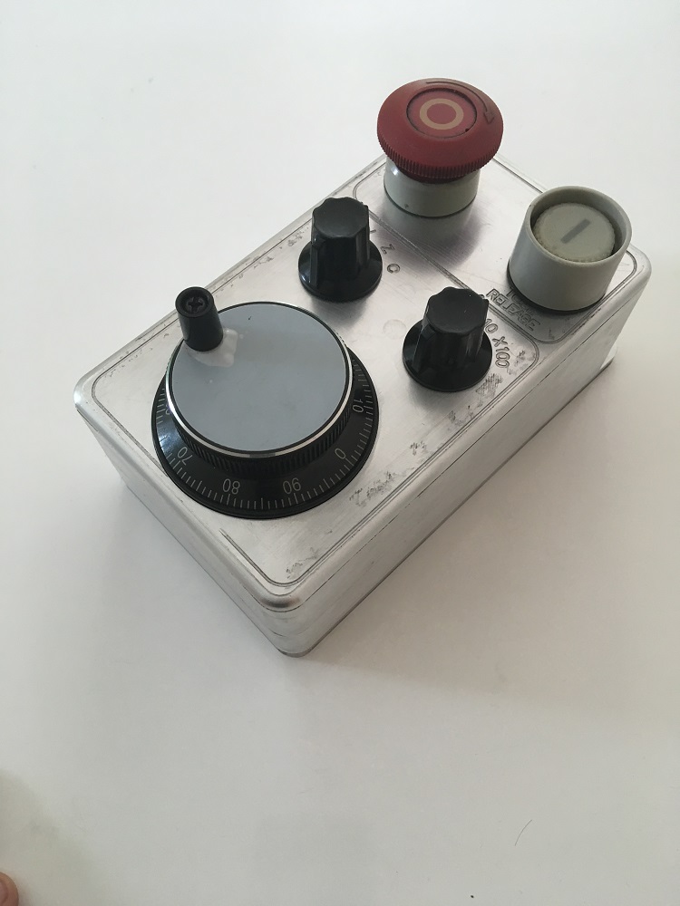
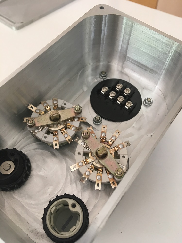
That is some excellent research. Once I finish my pendant housing, I'll get stuck back into tuning and try out indramats recommended values. Did you try that acceleration on yours yet?
I have only once short step of 8mm height to remove on the layer where the last 2 flute end mill broke, and then a half layer of 6mm depth. The only end mill I have which can reach is a brand new HSS 4 flute 16mm. I used the Clarkson to grind the shank diameter above the flutes, so that the shank won't rub on the walls.
Ill be using flood coolant, plus air blast to clear the chips. Should I just double the feed rate from 120 to 240mm/min for the switch from 2 flute to 4, retaining the same 1500 rpm, or would that be too aggressive?
Mike thanks for the input to the Tapmatic. Nice to see all that all info is on line for these. I will be replacing the MT#3 shank with a 40 taper shank. I'll either make/buy taper removal wedges or visit a friend who probably has them. I tried the Tapmatic suggestion of wacking the tang on the side with a hammer, but it is in too tight for that.
Mark
Last edit: 7 years 5 months ago by RotarySMP.
Please Log in or Create an account to join the conversation.
- Glemigobles
- Offline
- Elite Member
-
Less
More
- Posts: 201
- Thank you received: 18
7 years 5 months ago - 7 years 5 months ago #134255
by Glemigobles
Replied by Glemigobles on topic Retrofitting a 1986 Maho MH400E
Gonna try these today, time permitting. I *think* that the relation between the parameters described in the manuals and the following error wave displayed in halscope would be:
following error 1 - set P to get this value at the requested acc.
nod point - set I to decrease following error above this value
following error 2 - don't yet understand what to do with it
For Philips machine constants, these values are entered in microns and are very large (5,555mm, 2mm, 12mm). One thing to keep in mind is that the original controller stopped between lines of g-code for a set time in miliseconds, also entered in the MC. This made sure that the slide stopped at the correct point before continuing (gave time for the position loop to complete the move in the programmed place). Dunno how this would work with the trajectory planner and following errors.
I also think that your cutting problems might be related to the velocity curve of the moves calculated from your .ini file. Over time while milling a program such as your pendant housing (2 hours), the commanded feed is actually realised for a percentage of the time, while the remainder consists of moves in material at slower speeds that are the controller-derived ramps (joint.velocity-cmd trapezoid in halscope). That's bad for tool wear.
There's also the matter of the servo loop making a lot of miniscule corrections that might affect the stable operation of the drives. This is ofc pure conjecture on my part, which I'm taking from the perceptible and audible differences between various PID parameters I tested. In my case, the drives seem to be working much harder than they had, to achieve a comparatively far worse result. I can't imagine that it wouldn't have some effect on the machine's output, especially over a longer period.
Now in the case of your pendant housing, the endmill makes a lot of circular and helical moves and I'd wager that it's not always moving as fast as you programmed and that these slower feeds add up in the form of tool wear.
I can help you with your feeds and speeds for the new endmill, but first please check it for manufacturer and catalog number, or tell me whether the endmill is HSS (probably not), HSS-Co (cheaper) or HSS-PM (more expensive, superior performance). Also check for coating. These things make for a world of difference in setting the correct feeds and speeds.
EDIT: the tool info is usually there in some form on the cutter itself, you don't need the original box.
Last edit: 7 years 5 months ago by Glemigobles.
Please Log in or Create an account to join the conversation.
- RotarySMP
- Offline
- Platinum Member
-
Less
More
- Posts: 1635
- Thank you received: 595
7 years 5 months ago #134256
by RotarySMP
Replied by RotarySMP on topic Retrofitting a 1986 Maho MH400E
Someone (Andy P) informed my earlier in this thread that you do not use the Integral correction "I" when the drive closes the velocity loop like the Indramat. FF1 and FF2 are not the same as Ferror1 allowed Ferror2.My understanding is that FF1 is used to correct for stationary offset errors. You do not want your system to sit at the outside limit of an allowable tolerance. FF2 is used to damp the following error in the first instant of accel, and the last of decel.
I guess if you have an absolute stop at the end of every line of code, then Ferror on linear moves is irrelevant and can be very large, as the path is always correct, just a little behind during accel and then ahead during decel.. The only place where the Ferror could cause a deviation between the commanded path, and the actual tool path would be during G2/3 curves at high feedrates.
The trajectory planner of LinuxCNC is far more sophisticated, you define a width of the acceptable tool path tolerance, my simplistic understanding is that it will match the feedrate to the machines dynamic performance to remain within those boundaries.
Good point that my sluggish tuning is probably bad for cutter life. My presence is generally bad for cutter life
Too late, I already milled it out. Worked fine at 240 mm/min. The cutter is a Chinese end mill from CTCtools.biz. No info on the type of HSS (Assume no Co),no coating and no recommended cutting parameters. At €6 pop, you can see why I am pretty relaxed about killing them. I figured I'm better off using cheap cutters, until I get enough feel for the machine to stop doing the really stupid beginner mistakes (I killed two carbides - one be jogging it into steel, the second by letting it bounce lightly on work during tool release.



I guess if you have an absolute stop at the end of every line of code, then Ferror on linear moves is irrelevant and can be very large, as the path is always correct, just a little behind during accel and then ahead during decel.. The only place where the Ferror could cause a deviation between the commanded path, and the actual tool path would be during G2/3 curves at high feedrates.
The trajectory planner of LinuxCNC is far more sophisticated, you define a width of the acceptable tool path tolerance, my simplistic understanding is that it will match the feedrate to the machines dynamic performance to remain within those boundaries.
Good point that my sluggish tuning is probably bad for cutter life. My presence is generally bad for cutter life
I can help you with your feeds and speeds for the new endmill, but first please check it for manufacturer and catalog number, or tell me whether the endmill is HSS (probably not), HSS-Co (cheaper) or HSS-PM (more expensive, superior performance). Also check for coating. These things make for a world of difference in setting the correct feeds and speeds.
EDIT: the tool info is usually there in some form on the cutter itself, you don't need the original box.
Too late, I already milled it out. Worked fine at 240 mm/min. The cutter is a Chinese end mill from CTCtools.biz. No info on the type of HSS (Assume no Co),no coating and no recommended cutting parameters. At €6 pop, you can see why I am pretty relaxed about killing them. I figured I'm better off using cheap cutters, until I get enough feel for the machine to stop doing the really stupid beginner mistakes (I killed two carbides - one be jogging it into steel, the second by letting it bounce lightly on work during tool release.
Please Log in or Create an account to join the conversation.
Time to create page: 0.858 seconds