Retrofitting a 1986 Maho MH400E
- RotarySMP
-
 Topic Author
- Offline
- Platinum Member
-

Less
More
- Posts: 1627
- Thank you received: 595
10 Oct 2017 19:40 - 17 Oct 2017 08:25 #100161
by RotarySMP
Replied by RotarySMP on topic Retrofitting a 1986 Maho MH400E
I think I have finished the control panel design.
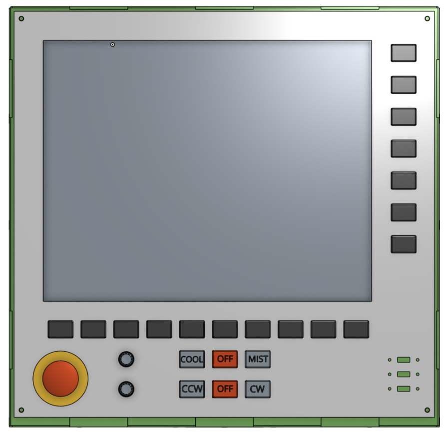
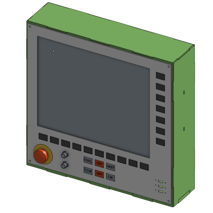
I can't bend parts this big and thick, so I am going up to 3mm steel, and will weld it together. The baseplate is 10mm, to bolt onto the existing arm attachment.
Mark
I can't bend parts this big and thick, so I am going up to 3mm steel, and will weld it together. The baseplate is 10mm, to bolt onto the existing arm attachment.
Mark
Last edit: 17 Oct 2017 08:25 by RotarySMP.
Please Log in or Create an account to join the conversation.
- RotarySMP
-
Topic Author
- Offline
- Platinum Member
-
Less
More
- Posts: 1627
- Thank you received: 595
15 Oct 2017 16:22 #100396
by RotarySMP
Replied by RotarySMP on topic Retrofitting a 1986 Maho MH400E
This weekend I got the touchscreen working:
forum.linuxcnc.org/9-installing-linuxcnc...nding-story?start=10
and designed the clamp blocks to hold the Heidenhain EXE. They are printing now.
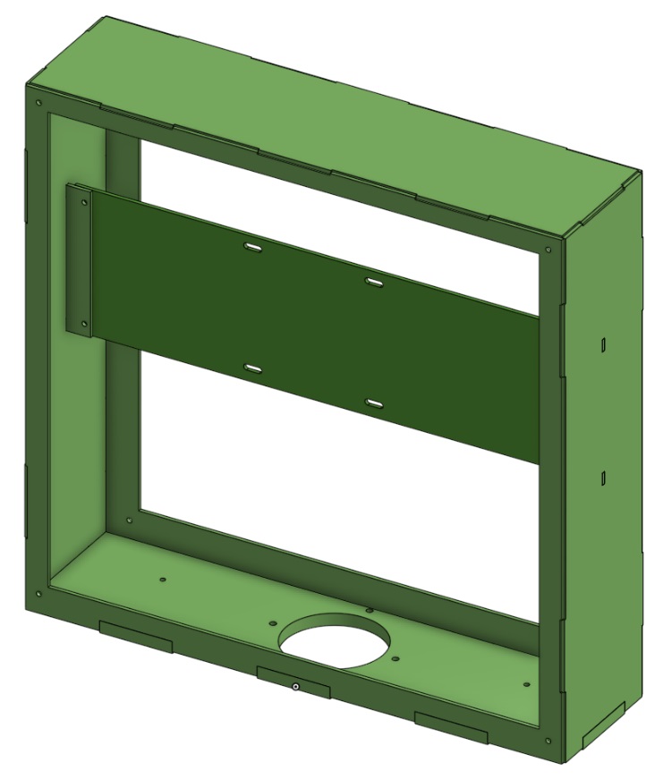
Also finished off the drawings of the sheet metal parts to make the new control housing. The DXF's are ready for the Laser.
Mark
forum.linuxcnc.org/9-installing-linuxcnc...nding-story?start=10
and designed the clamp blocks to hold the Heidenhain EXE. They are printing now.
Also finished off the drawings of the sheet metal parts to make the new control housing. The DXF's are ready for the Laser.
Mark
Please Log in or Create an account to join the conversation.
- RotarySMP
-
Topic Author
- Offline
- Platinum Member
-
Less
More
- Posts: 1627
- Thank you received: 595
17 Oct 2017 06:44 - 17 Oct 2017 07:05 #100457
by RotarySMP
Replied by RotarySMP on topic Retrofitting a 1986 Maho MH400E
Yesterday I cut and installed the cable channel onto the backing plate which carries the PC and Mesa 7i77.

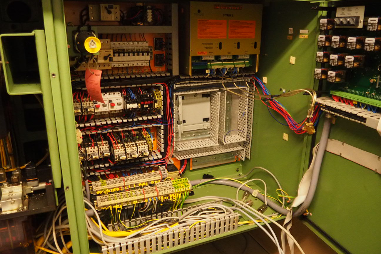
Then started removing unnecessary wiring, such as the ones for the tape reader, the MAHO pendant etc. Terminal block 19x5 was removed. I still need to pull the old CGA cable out of the conduit to the controller, but won't do that before I have the new cable to be pulled through.
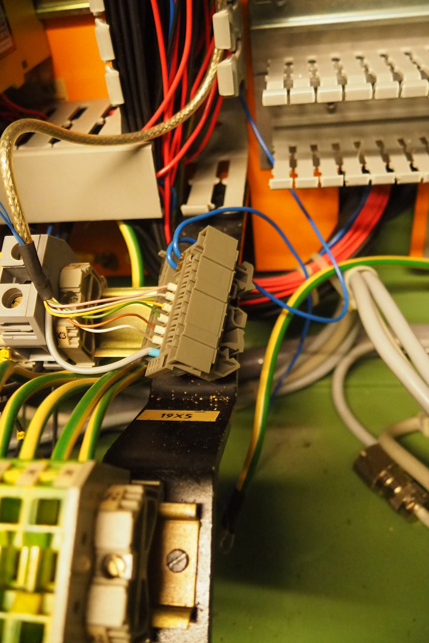
I then installed that new relay for drive enable which I called 19K2, and wired it up.
I was also working on installing the 5VDC PSU (6T2) to power the encoders and the 7i77. I'm using a Brother P-touch to label both ends of each wire, and covering the label with heatshrink.
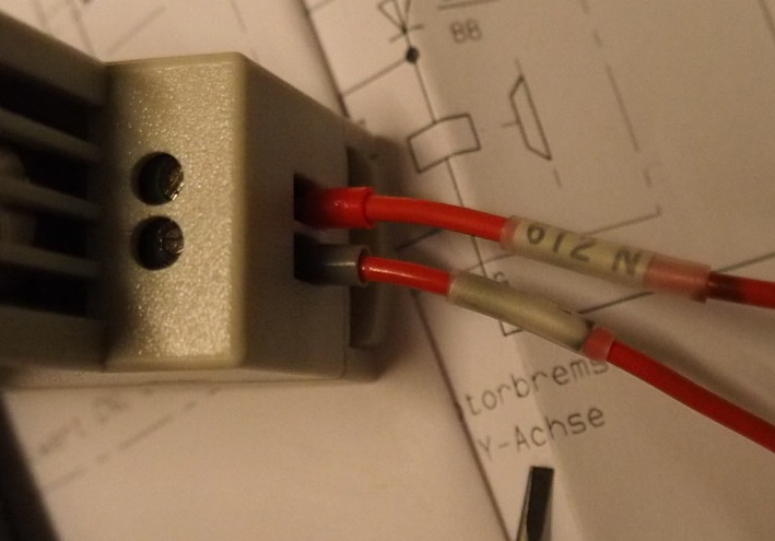
I made a mistake on drawing 8 (see atached update). I called the 5VDC output from PSU (6T2) terminals 300 and 301, but found those those already exist on the MAHO 28X3 as 24V connections, so I had to rename them to 400 and 401. I'll probably add those two terminal blocks to the end of that DIN rail where the 19x5 was removed. Also, I show that little PSU (6T2) connected to 110VAC through terminals 150 and 156. On my terminal block strip, there were no free connections to 156, but there was one free on 151, which is the same 110VAC rail.
Mark
Then started removing unnecessary wiring, such as the ones for the tape reader, the MAHO pendant etc. Terminal block 19x5 was removed. I still need to pull the old CGA cable out of the conduit to the controller, but won't do that before I have the new cable to be pulled through.
I then installed that new relay for drive enable which I called 19K2, and wired it up.
I was also working on installing the 5VDC PSU (6T2) to power the encoders and the 7i77. I'm using a Brother P-touch to label both ends of each wire, and covering the label with heatshrink.
I made a mistake on drawing 8 (see atached update). I called the 5VDC output from PSU (6T2) terminals 300 and 301, but found those those already exist on the MAHO 28X3 as 24V connections, so I had to rename them to 400 and 401. I'll probably add those two terminal blocks to the end of that DIN rail where the 19x5 was removed. Also, I show that little PSU (6T2) connected to 110VAC through terminals 150 and 156. On my terminal block strip, there were no free connections to 156, but there was one free on 151, which is the same 110VAC rail.
Mark
Last edit: 17 Oct 2017 07:05 by RotarySMP.
Please Log in or Create an account to join the conversation.
- RotarySMP
-
Topic Author
- Offline
- Platinum Member
-
Less
More
- Posts: 1627
- Thank you received: 595
17 Oct 2017 11:10 - 17 Oct 2017 11:27 #100460
by RotarySMP
Replied by RotarySMP on topic Retrofitting a 1986 Maho MH400E
Since the 7i77 has dedicate drive enable switching on the TB 5 connector, there is no point wasting a general I/O pin on that. I changed drawing 26 to move drive enable from the 7i84 onto the 7i77 TB5-1
Per the mesa manual...
Note that the enable outputs are polarized and can be
damaged with reverse polarity. For active high drive enables, ENAN+ should go to the
appropriate positive power supply and ENAN- to the drive enable input. For active low
enable drives, ENAN+ should go the the drive enable and ENAN- to control power ground.
Looks like this relay doesn't switch field power, but rather just switches TB5 pins 1 and 2, so we'll need to run an extra +24V line to the 7i77 TB5-2 to close that circuit.
Please check whether I have this round the right way...
Mark
Last edit: 17 Oct 2017 11:27 by RotarySMP.
Please Log in or Create an account to join the conversation.
- drimaropoylos
- Offline
- Elite Member
-

Less
More
- Posts: 265
- Thank you received: 40
17 Oct 2017 13:06 #100466
by drimaropoylos
Replied by drimaropoylos on topic Retrofitting a 1986 Maho MH400E
I thing it’s correct, but we haven’t find solution to “chicken/ egg problem”.
Good work
John
Good work
John
Please Log in or Create an account to join the conversation.
- drimaropoylos
- Offline
- Elite Member
-
Less
More
- Posts: 265
- Thank you received: 40
17 Oct 2017 13:25 - 17 Oct 2017 13:37 #100468
by drimaropoylos
Replied by drimaropoylos on topic Retrofitting a 1986 Maho MH400E
I think we need to disconnect the 7A1 from the 19K1 chain and use it to feed the axis.0.amp-fault-in pin in the hal file.
Something like net Xfault-in hm2_5i25.0.7i77.0.0.input-12=> axis.0.amp-fault-in. but reversed. (Reverse the output)
Something like net Xfault-in hm2_5i25.0.7i77.0.0.input-12=> axis.0.amp-fault-in. but reversed. (Reverse the output)
Last edit: 17 Oct 2017 13:37 by drimaropoylos.
Please Log in or Create an account to join the conversation.
- drimaropoylos
- Offline
- Elite Member
-
Less
More
- Posts: 265
- Thank you received: 40
17 Oct 2017 13:28 #100469
by drimaropoylos
Replied by drimaropoylos on topic Retrofitting a 1986 Maho MH400E
So when the amplifier is in trouble it will tell the pin axis.0.amp-fault-in to stop everything and put on estop the machine.
Please Log in or Create an account to join the conversation.
- drimaropoylos
- Offline
- Elite Member
-
Less
More
- Posts: 265
- Thank you received: 40
17 Oct 2017 13:35 #100470
by drimaropoylos
Replied by drimaropoylos on topic Retrofitting a 1986 Maho MH400E
I need a day off work to sit down and study the drawings, to propose a solution to this.
Please Log in or Create an account to join the conversation.
- RotarySMP
-
Topic Author
- Offline
- Platinum Member
-
Less
More
- Posts: 1627
- Thank you received: 595
17 Oct 2017 14:36 - 17 Oct 2017 15:11 #100471
by RotarySMP
Replied by RotarySMP on topic Retrofitting a 1986 Maho MH400E
I'd like to keep the MAHO E-Stop and electrics as original as possible. How about this idea...
Button SH-1 was the Phillips start switch, for me this is "E-Stop release". I will probably hard wire it in the top RH position of my control panel.
Have LinuxCNC set TB2-17 - "CNC-Ready" as soon as it starts, and hold it on as long as there is no LinuxCNC fault. I think this is what the Phillips did. Is there an existing HAL signal for "LinuxNC is running without fault"?
net CNC_ready.LinuxCNC is now running => hm2_5i25.0.7i77.0.0.output.08 # sorry, time I start learning HAL syntax properly
sets CNC_ready.LinuxCNC is now running 1
So 19K1 is primed to close, waiting for "7A1" Bb1-Bb2 to close.
Then, when the SH-1 is pushed the Indramat gets power via the 7K1/7K2/7K3 E-Stop relays, and closes its "7A1" Bb1-Bb2 contact in the "NC-Ready" chain, thus 19k1 can close and the system is on and should remain latched even after SH-1 is released.
If the indramat fails, it opens "7A1" Bb1-Bb2, which releases 19K1. If the LinuxCNC has a fault or fails, 19K1 is released directly. Either way the machine fails into E-Stop per MAHO's original design, without software intervention.
This way, the "drive enable" is only doing that single function, and we don't need to change anythig in the E-Stop wiring.
Mark
Last edit: 17 Oct 2017 15:11 by RotarySMP.
Please Log in or Create an account to join the conversation.
- drimaropoylos
- Offline
- Elite Member
-
Less
More
- Posts: 265
- Thank you received: 40
17 Oct 2017 15:08 #100475
by drimaropoylos
Replied by drimaropoylos on topic Retrofitting a 1986 Maho MH400E
If we leave the wiring as is, then the indramat must energize with start button, not separately. Or as soon we release the start button then everything is deactivated again.
Please Log in or Create an account to join the conversation.
Moderators: piasdom
Time to create page: 0.547 seconds