Retrofitting a 1986 Maho MH400E
- Glemigobles
- Offline
- Elite Member
-

Less
More
- Posts: 201
- Thank you received: 18
12 May 2019 10:14 #133539
by Glemigobles
Replied by Glemigobles on topic Retrofitting a 1986 Maho MH400E
If you do plunge milling as suggested, remember you have to first drill (or rather helical mill; I'm still thinking 2,5D toolpaths) a point of entry, since you're not starting from the outside of the material like John does in the NYCCNC video. I also don't know how well that strategy would work with a standard HSS endmill, they can't take the same abuse that carbide bits do.
Thanks a lot for the files, I'm down to connecting the EXE now, then the config begins!
Thanks a lot for the files, I'm down to connecting the EXE now, then the config begins!
Please Log in or Create an account to join the conversation.
- RotarySMP
-
 Topic Author
- Offline
- Platinum Member
-

Less
More
- Posts: 1627
- Thank you received: 595
12 May 2019 11:27 - 12 May 2019 11:41 #133551
by RotarySMP
Replied by RotarySMP on topic Retrofitting a 1986 Maho MH400E
Looks like 20 year old version of FeatureCAM doesn't offer a plunge milling strategy. Wont cutting 11mm wide x 8mm deep also be a huge bending load?Like killed my 14mm mill?
FeatureCAM is estimating nearly 3 hours of cutting time. Is it realistic to expect a new HSS end mill to last that long, or should break the tool path up and touch it up on the Clarkson it each hour or so?
Mark
FeatureCAM is estimating nearly 3 hours of cutting time. Is it realistic to expect a new HSS end mill to last that long, or should break the tool path up and touch it up on the Clarkson it each hour or so?
Mark
Last edit: 12 May 2019 11:41 by RotarySMP.
Please Log in or Create an account to join the conversation.
- Glemigobles
- Offline
- Elite Member
-
Less
More
- Posts: 201
- Thank you received: 18
12 May 2019 13:12 #133556
by Glemigobles
Replied by Glemigobles on topic Retrofitting a 1986 Maho MH400E
Usually, endmills are designed to work 2 hours at their maximum parameters. I'd say at 3 hours you're safe.
Please Log in or Create an account to join the conversation.
- RotarySMP
-
Topic Author
- Offline
- Platinum Member
-
Less
More
- Posts: 1627
- Thank you received: 595
12 May 2019 14:32 #133559
by RotarySMP
Replied by RotarySMP on topic Retrofitting a 1986 Maho MH400E
thanks Im cutting the third level now. your recommended feeds, depth width and and speeds are working well
Please Log in or Create an account to join the conversation.
- RotarySMP
-
Topic Author
- Offline
- Platinum Member
-
Less
More
- Posts: 1627
- Thank you received: 595
12 May 2019 18:29 #133586
by RotarySMP
Replied by RotarySMP on topic Retrofitting a 1986 Maho MH400E
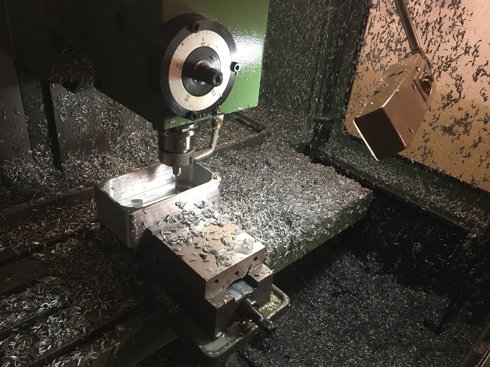
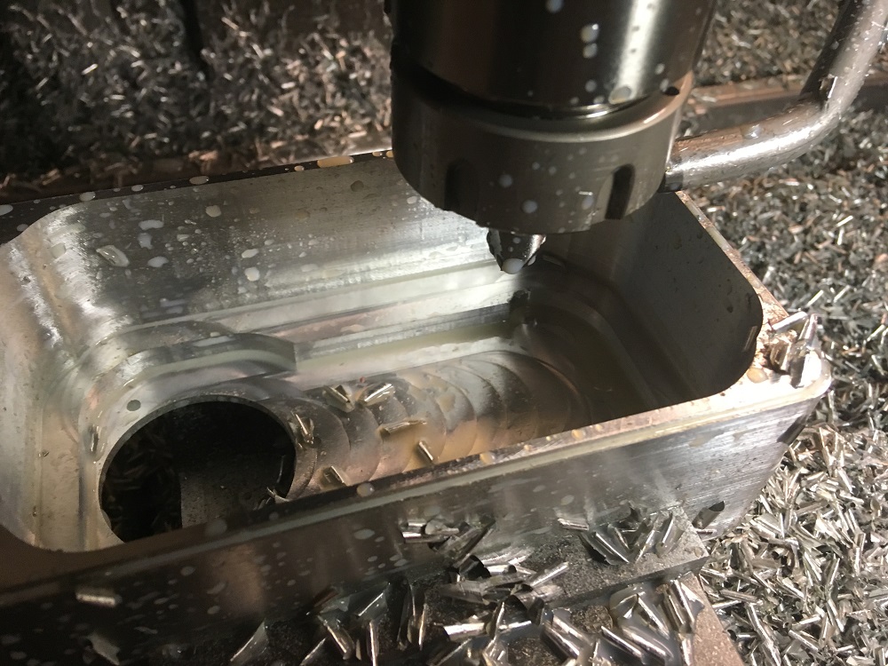
I got down to the 6th level of end mill hell, before the 16mm two flute left me.
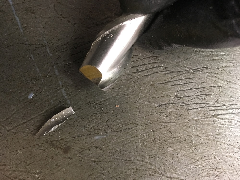
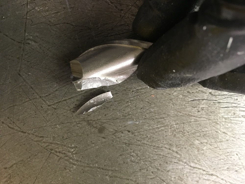
A whole flute broke out. and then the mill broke off almost immediately.
I was not doing anything special, no crash, no unusual load at that point. There was an audible squeaky chatter whenever it was in the full 10mm width of cut. It wasn't a coolant fail, as it was flooded the whole time. I used a air gun and baby sat the part, blasting the chips away so it wouldn't be recutting chips. Actually this 6th layer broke though to the encoder cut out, so it cleared though the hole much better than other layers had. I should have drilled a big hole first thing, do give the coolant and chips a way out.
At least the part is salvagable.
Mark
Please Log in or Create an account to join the conversation.
- Glemigobles
- Offline
- Elite Member
-
Less
More
- Posts: 201
- Thank you received: 18
13 May 2019 08:26 - 13 May 2019 08:43 #133630
by Glemigobles
Replied by Glemigobles on topic Retrofitting a 1986 Maho MH400E
How long did the endmill work to get to that point? Also relevant, what kind of toolpath did you use to get from one step to the next? Did it plunge straight down, like in a canned cycle for a rectangular pocket (which it then should reduce the feed to 1/2 the programmed one), or more preferrably, did it mill helically to reduce wear on the endmill tip?
Threre are unfortunately several factors that might have caused the tool to break. But, in my admittedly limited experience, whenever you hear or see something that's a little bit off (like the squeeky noise you described), it's best to remove the endmill and sharpen it. That's because you usually only have a limited window of opportunity before the any wear becomes too much and the whole thing breaks and you have to scrap it.
I try to remove my endmills when I see undesirable behaviour or less-than-clean edges on parts. Since I don't have a tool grinder, I collect a bunch of dull endmills and ship them to be sharpened at an outside company. In my case, I get a sharpened tool at 1/3 the cost of a new one, so it pays off real well.
On the retrofit front, here's a question regarding starting the machine. I notice that in your hal configuration you have a machine is on signal on the 7i77 (I think it's pin 04 negative). On your machine, a CAT5 cable connects the 7i84 to TB6 on the 7i77. But because of the added 7i74, my config is a little different, I think. The 7i77 only physically interfaces with the drives and encoders, whereas the 7i84 is connected to P2 on the 5i25 in the PCI slot. It would seem that I should change the pin in the hal file to have any signal there. My 7i77 only has connections on TB3 and TB5.
Am I correct to assume that I should change the pin to TB2 17 from the schematic, which is output 8 on the 7i84?
This isn't clear to me because your file does call out the 7i84 pins specifically. And yet there's no escaping the fact that my 7i77 isn't actually connected to anything else than the drives and encoders.
EDIT: sorry, it's not the machine on signal, it's the connection between the virtual button in gmoccapy and 3SH1, the hydraulic start on the panel. In your machine start up video, you have all the start buttons in the LinuxCNC virtual panel (albeit connected to your physical buttons).
EDIT2: Sorry, my fault, I see that it's all related to your custom control panel. I kind of skipped over that part in your manual.
Last edit: 13 May 2019 08:43 by Glemigobles.
Please Log in or Create an account to join the conversation.
- Glemigobles
- Offline
- Elite Member
-
Less
More
- Posts: 201
- Thank you received: 18
13 May 2019 10:56 #133632
by Glemigobles
Replied by Glemigobles on topic Retrofitting a 1986 Maho MH400E
I'm reading through this thread again to better understand what I'm supposed to do with the added Finder Relay (19K2) to power on the machine. I'd appreciate some dumbed-down instructions, as I've never wired a relay before, Should the A1 and A2 coil terminals be wired to power (24V?) and ground, and then the 207 cable snipped and wired into Common and NO? I'm going off of googe here to understand Mark's schematic.
Please Log in or Create an account to join the conversation.
- RotarySMP
-
Topic Author
- Offline
- Platinum Member
-
Less
More
- Posts: 1627
- Thank you received: 595
13 May 2019 11:50 - 13 May 2019 12:00 #133635
by RotarySMP
Replied by RotarySMP on topic Retrofitting a 1986 Maho MH400E
How long did the endmill work to get to that point?
- About two hours.
Also relevant, what kind of toolpath did you use to get from one step to the next? Did it plunge straight down, like in a canned cycle for a rectangular pocket (which it then should reduce the feed to 1/2 the programmed one), or more preferrably, did it mill helically to reduce wear on the endmill tip?
- Helical milling of a about a 40mm diamter circle at 1/2 feedrate , then circular tool paths, so that the tool never exceeded the 10mm width of engagement.
Threre are unfortunately several factors that might have caused the tool to break.
- But the one overriding risk factor is a loose nut. Between my ears")
Good pickup. Just took a look at my schematics, and notes and HAL, and it looks like I am outputting the "Machine-is-on" status three times.
I had already started to answer this and reread you edits:
You need a hard wired button to release e-Stop. This is the hyd button on the original MAHO/Phillips. You also need to digitally tell LinuxCNC to release E-Stop. So my top physical button has two poles. One connects to the original MAHO Hyd button wiring. The other (thorugh the matric_kb) tells LinuxCNC it has been pushed.
In addition, you then need a digital output signal from LinuxCNC to latch the machine on.
Until you get a control panel set up, you can do the three finger death punch. On finger on the Hyd button, one on the touch screen LinuxCNC E-Stop release button, and one on the LinuxCNC machine on button. You could probably write a little HALfui to do all that with a single button, but I kind of liked the MAHO heritage of need a dual button press
One:This one is pin 209 connected through ribbon cable wire 3 to the 7i84 TB2-17 (hm2_5i25.0.7i84.0.2.output-08)
Two:
I also thought I would need to give LinuxCNC control of the drive enable and the Z axis brake.For that purpose I added that 19K2 relay, (see schematic sheet 6 and 26)
According to this schematic I connected this to TB5-2 which is one of the MESA 7i77 common drive enable pins. At least in my HAL I have nothing set up to control that output. (I need use HALshow to see what pin it is?) I am not not sure that schematic is correct. I'll need to take a look at that tonight
My expectation was that the:
- Top button push would release e-stop, (the MAHO Hydraulic button) and
- second button would enable drives, release the brake and latch the system on.
I found that the Indramat powers up on the top button push, so this added relay only controls the Z brake.
You can of course rewire these to the 7i84, and assign the applicable output in the HAL. My logic was to use the 7i84 to connect everything on the MAHO relay board which is on the door, and the 7i77 terminals to connect everything in the cabinet rack, to minimise the wiring which has to move with the door. LinuxCNC doesn't care whether I/O pins from the 7i77 or 7i84 are used. They are all the same for this purpose.
You also mentioned the "machine is on signal on the 7i77 (I think it's pin 04 negative)", this is feedback in the other direction. It is the MAHO telling the controller it is on, so it is an input into a MESA card.
To wire up the 19K2 relay, find the 7K2 relay, find its terminal 44. That wire goes to terminal 207. Disconnect that wire and connect it to 19K2 pin 14. You will have to dig that wire out of the cable channel. Then run a new length of wire from 19K2 pin 11 to 7K2 Pin 44.
Then run a new wire from one of the 201 to 19K2 A2 and a second wire from 19K2 A1 to a mesa output pin. See above, I have a feeling that this got connected to a normal output pin (TB8-17) rather than TB5-1 as shown on the schematic.
- About two hours.
Also relevant, what kind of toolpath did you use to get from one step to the next? Did it plunge straight down, like in a canned cycle for a rectangular pocket (which it then should reduce the feed to 1/2 the programmed one), or more preferrably, did it mill helically to reduce wear on the endmill tip?
- Helical milling of a about a 40mm diamter circle at 1/2 feedrate , then circular tool paths, so that the tool never exceeded the 10mm width of engagement.
Threre are unfortunately several factors that might have caused the tool to break.
- But the one overriding risk factor is a loose nut. Between my ears
Good pickup. Just took a look at my schematics, and notes and HAL, and it looks like I am outputting the "Machine-is-on" status three times.
I had already started to answer this and reread you edits:
You need a hard wired button to release e-Stop. This is the hyd button on the original MAHO/Phillips. You also need to digitally tell LinuxCNC to release E-Stop. So my top physical button has two poles. One connects to the original MAHO Hyd button wiring. The other (thorugh the matric_kb) tells LinuxCNC it has been pushed.
In addition, you then need a digital output signal from LinuxCNC to latch the machine on.
Until you get a control panel set up, you can do the three finger death punch. On finger on the Hyd button, one on the touch screen LinuxCNC E-Stop release button, and one on the LinuxCNC machine on button. You could probably write a little HALfui to do all that with a single button, but I kind of liked the MAHO heritage of need a dual button press
One:
#Output MACHINE-IS-ON to latch the 19K1 relay.
net machine-is-on hm2_5i25.0.7i84.0.2.output-08Two:
I also thought I would need to give LinuxCNC control of the drive enable and the Z axis brake.
# --- Z BRAKE ---
#Release Z brake when machine-is-on
net machine-is-on => hm2_5i25.0.7i77.0.0.output-0
According to this schematic I connected this to TB5-2 which is one of the MESA 7i77 common drive enable pins. At least in my HAL I have nothing set up to control that output. (I need use HALshow to see what pin it is?) I am not not sure that schematic is correct. I'll need to take a look at that tonight
My expectation was that the:
- Top button push would release e-stop, (the MAHO Hydraulic button) and
- second button would enable drives, release the brake and latch the system on.
I found that the Indramat powers up on the top button push, so this added relay only controls the Z brake.
You can of course rewire these to the 7i84, and assign the applicable output in the HAL. My logic was to use the 7i84 to connect everything on the MAHO relay board which is on the door, and the 7i77 terminals to connect everything in the cabinet rack, to minimise the wiring which has to move with the door. LinuxCNC doesn't care whether I/O pins from the 7i77 or 7i84 are used. They are all the same for this purpose.
You also mentioned the "machine is on signal on the 7i77 (I think it's pin 04 negative)", this is feedback in the other direction. It is the MAHO telling the controller it is on, so it is an input into a MESA card.
To wire up the 19K2 relay, find the 7K2 relay, find its terminal 44. That wire goes to terminal 207. Disconnect that wire and connect it to 19K2 pin 14. You will have to dig that wire out of the cable channel. Then run a new length of wire from 19K2 pin 11 to 7K2 Pin 44.
Then run a new wire from one of the 201 to 19K2 A2 and a second wire from 19K2 A1 to a mesa output pin. See above, I have a feeling that this got connected to a normal output pin (TB8-17) rather than TB5-1 as shown on the schematic.
Attachments:
Last edit: 13 May 2019 12:00 by RotarySMP.
The following user(s) said Thank You: Glemigobles
Please Log in or Create an account to join the conversation.
- Glemigobles
- Offline
- Elite Member
-
Less
More
- Posts: 201
- Thank you received: 18
13 May 2019 13:33 - 13 May 2019 14:22 #133639
by Glemigobles
Replied by Glemigobles on topic Retrofitting a 1986 Maho MH400E
Okay, I wired the relay per your instructions. Now when I press the 3SH-1 button when the controller isn't running, one of the axes moves (I think it's the Z brake release) and I can't hear the drives humming. Is this what the relay should do outside of LinuxCNC? I.e. drive enable and brake release are separated and everything is controlled by the Mesa cards so LinuxCNC must be on?
Before I test this further, I have to take the covers off the Maho and manually move the axes to a more central position, this is getting dangerous.
EDT: Maybe I should also clarify that since I didn't remove the panel or the pendant, both E-stop buttons still function (just not the rest of the keys, they'd have to be connected and configured), just like the 3SH-1.
Last edit: 13 May 2019 14:22 by Glemigobles.
Please Log in or Create an account to join the conversation.
- Glemigobles
- Offline
- Elite Member
-
Less
More
- Posts: 201
- Thank you received: 18
13 May 2019 15:11 - 13 May 2019 15:29 #133643
by Glemigobles
Replied by Glemigobles on topic Retrofitting a 1986 Maho MH400E
"You also need to digitally tell LinuxCNC to release E-Stop. So my top physical button has two poles. One connects to the original MAHO Hyd button wiring. The other (thorugh the matric_kb) tells LinuxCNC it has been pushed."
How do I tell LinuxCNC that I pressed the hydraulics button and the estop is released if I retained the original button? Is there any additional wiring to be done, or should I configure a hal command?
As it is now, if I use the E-stop chain code from you hal configuration, LinuxCNC can't release the E-stop using the gui, telling me that an external E-stop is on. This remains the same even if I press the hydaulics button. I was under the impression that one of the relay board wires connected to the 7i84 was responsible for communicating to the controller that 3SH-1 was pressed.
On the other hand, a software e-stop has no connection to the hardware. I'm finding this to be very confusing despite your instructions, which usually means I forgot to do something important.
On the plus side, when the brake is released and the axis moves, LinuxCNC does show it moving on the DRO and plot. This means at least that the encoders are working, since the drives remain off.
EDIT: should there actally be 24 V power connected to TB5 2 to enable the drives?
Last edit: 13 May 2019 15:29 by Glemigobles.
Please Log in or Create an account to join the conversation.
Moderators: piasdom
Time to create page: 0.397 seconds