
- Posts: 109
- Thank you received: 2

Please Log in or Create an account to join the conversation.

Please Log in or Create an account to join the conversation.
Please Log in or Create an account to join the conversation.
2. The Base Thread, which the step generator runs in, runs by default at 40khz. For a step on and off this takes two cycles so the fastest theoretically is 20khz. Below is a trace of both threads. There is some idle cpu time, but how fast do we need to go. On a typical 3D printer setup this is > 200mm sec.
At these higher speeds your setup needs to be done well to avoid following errors. ie stepgen acceleration set appropriately , joint velocity > max velocity so that the joint can actually make up any following error. Marlin and other firmwares don't monitor the actual step generation and just push out pulses. Remora does, so the configuration needs to be such to allow the control loop to do its job.
what resolution is that screen you are using? 1080*640?This is the beginning of my stand alone controller
Please Log in or Create an account to join the conversation.
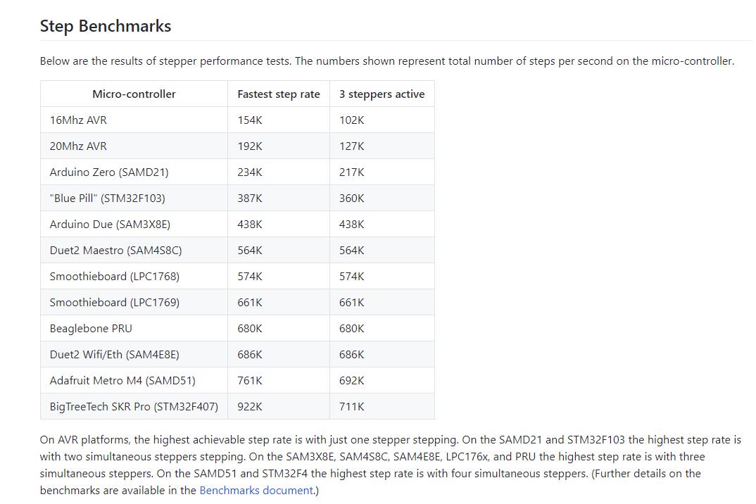
LPC17XX can do much faster step rates ??? where is the bottleneck. What's the point of 25khz the built-in I/O of the RPI can do that.
Please Log in or Create an account to join the conversation.
Since Rommel shared his STM32 port I have been tempted to have a crack at this. I've now got a BTT SKR v2 with the STM32F407 on the way. 168Mhz is attractive to start testing speeds but how fast do we really need...Can't the LPC17xx handle higher real time thread rates? OH! Maybe not , only 100/120 MHZ ARM core.
www.nxp.com/products/processors-and-micr...ackage:LPC1768FBD100
We should be able to fix this using STM32.
Please Log in or Create an account to join the conversation.
