Closed loop with linear encoders but still backlash?
- PCW
-

- Offline
- Moderator
-

Less
More
- Posts: 17917
- Thank you received: 5246
25 Dec 2019 16:43 - 25 Dec 2019 17:23 #153199
by PCW
Replied by PCW on topic Closed loop with linear encoders but still backlash?
Theoretically, I term is not needed, The reason for this is that the stepgen has a very wide
velocity dynamic range (the 7I95 stepgens minimum settable frequency is ~.025 Hz)
With the OPs 1200 steps/mm settings and P term of 90, the minimum
correctable error is ~.2 nanometers, way below the scale resolution
I term may be useful for analog or low resolution velocity mode systems
I would check that
1. Your DRO is reading actual rather than commanded position
2. You don't have lost motion between where you are measuring and the scale
Because if you are reading actual position and it has no error, the scale is in the correct position but
the rest of your mechanics are not. This might be the result of loose gibs on a dovetail way system.
Last edit: 25 Dec 2019 17:23 by PCW. Reason: use "actual" instead of "feedback" since thats what the display options are called
Please Log in or Create an account to join the conversation.
- Hakan
- Offline
- Platinum Member
-

Less
More
- Posts: 1317
- Thank you received: 453
25 Dec 2019 18:24 #153200
by Hakan
Replied by Hakan on topic Closed loop with linear encoders but still backlash?
What I see myself is that there is after all some time needed to catch up on the backlash, or the following error.
When the slides go really slow there is virtually no following error, as the speed increases there is more and more.
It is not realistic to expect no following error at full speed. But at low speed one should expect really low error.
Set Backlash=0 in the ini file, let the feedback handle that instead.
Please Log in or Create an account to join the conversation.
- Gnevko
- Offline
- Senior Member
-

Less
More
- Posts: 59
- Thank you received: 10
23 Jan 2020 19:52 #155568
by Gnevko
Replied by Gnevko on topic Closed loop with linear encoders but still backlash?
Today I had time to make some more additional tests on my machine. And of course as usual I am a little bit confused. The test is very simple:
1) to take a parallel with exactly 20.00 mm wide and set X axis to zero on the left side:
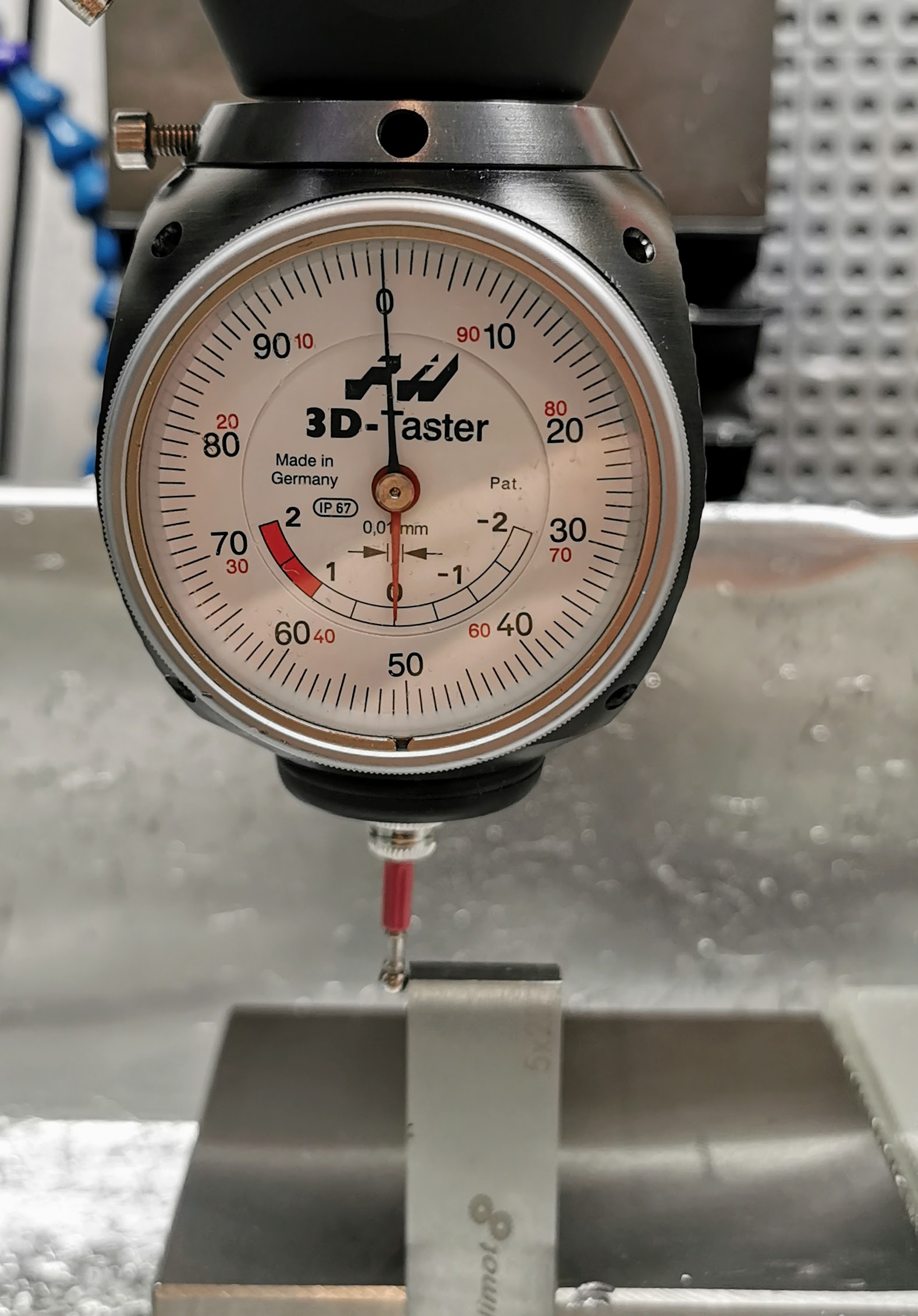
2) after that navigate to the right side of the parallel and read the value from DRO.
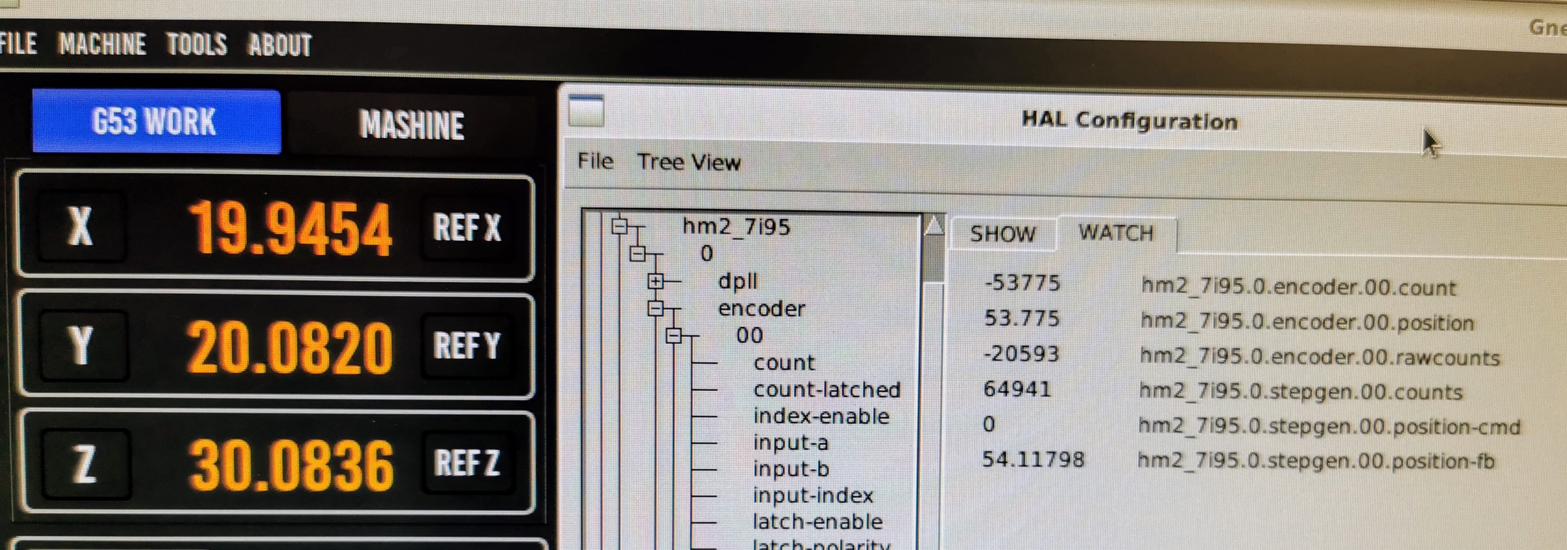
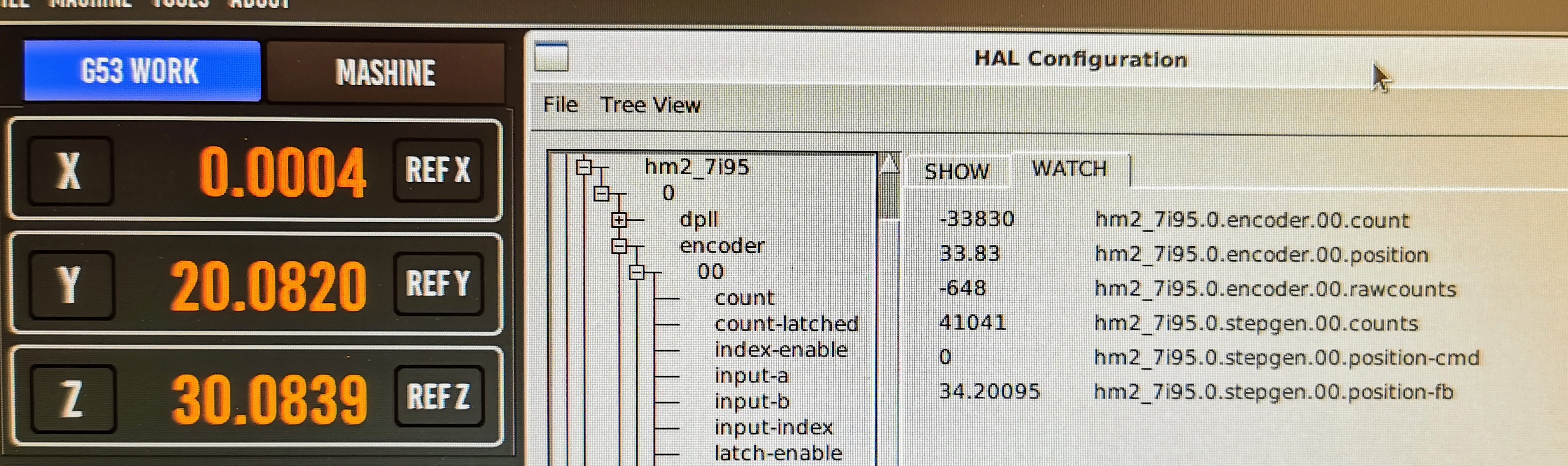
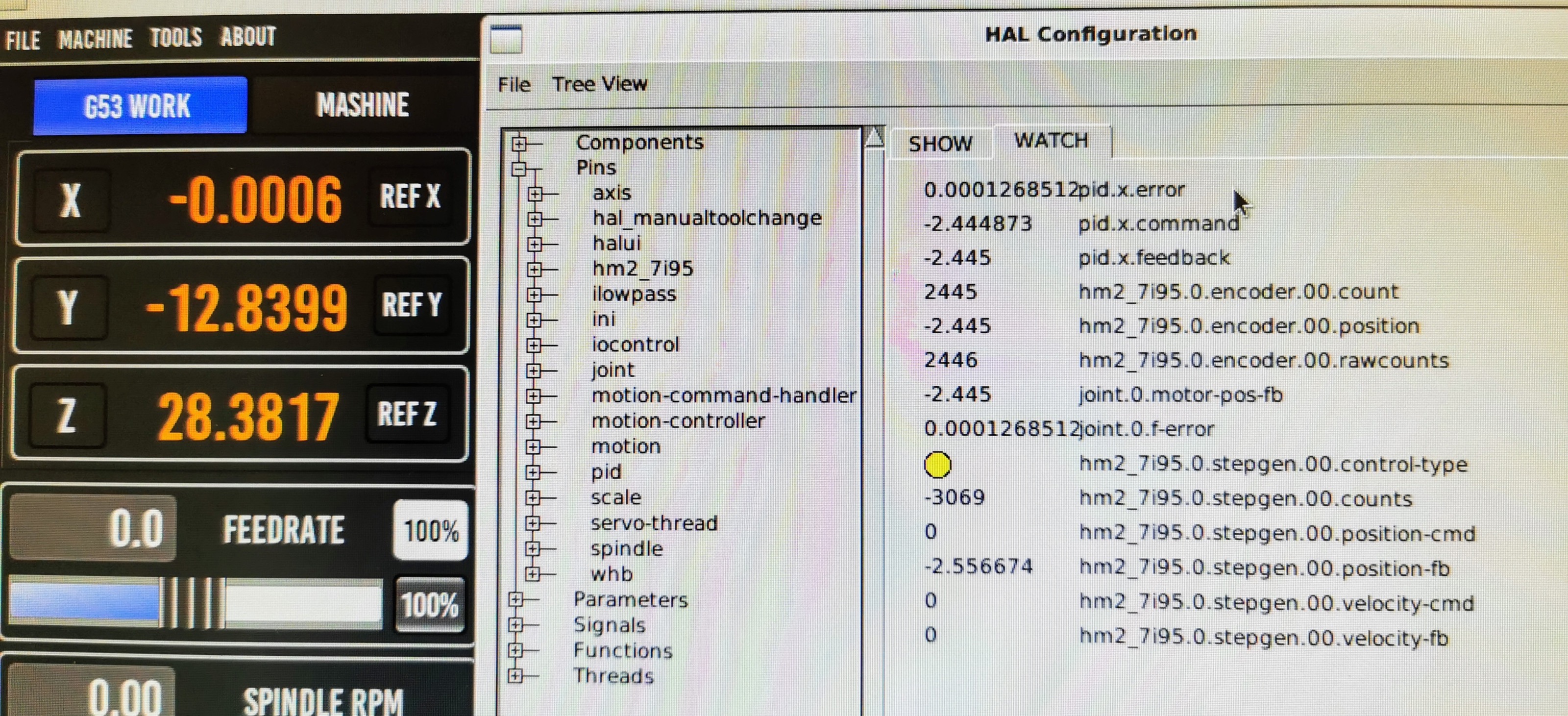
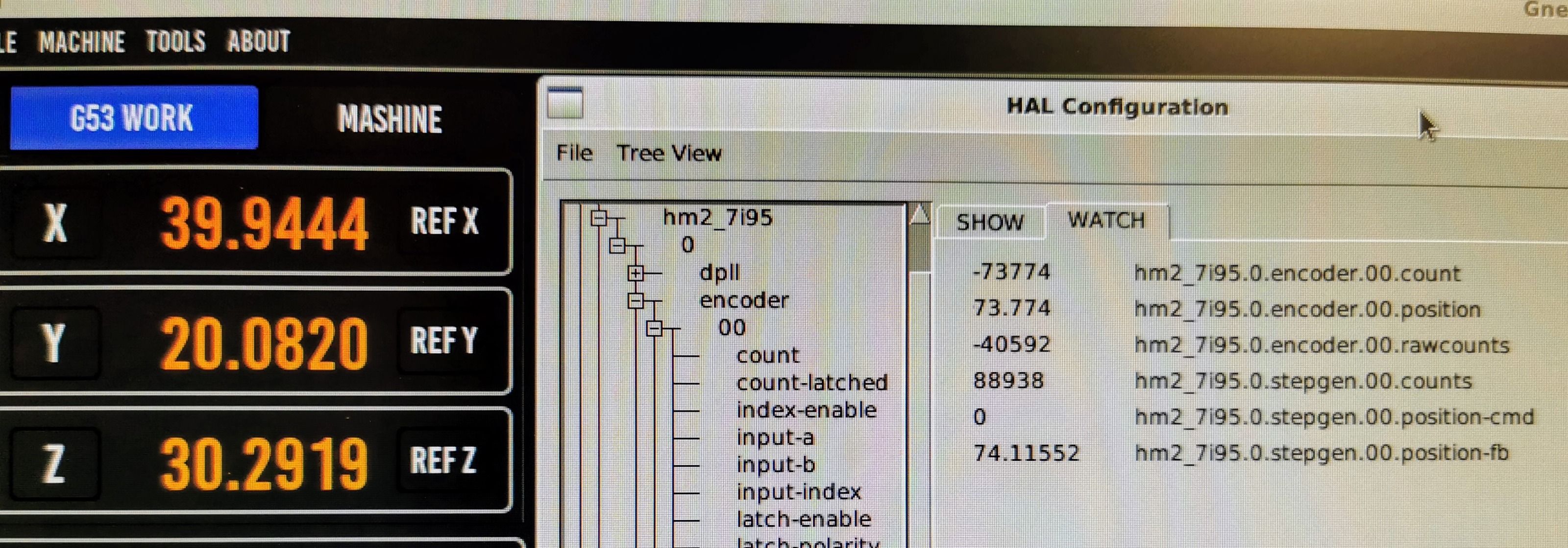
I expected to see something about 20.00mm (+- 0.01) but as you can see it is only 19.945mm
With is also very strange - the encoder position is not the same as stepgen.position-fb.
HAL Configuration for X:
MPG Configuration (because I made the navigation with it):
1) to take a parallel with exactly 20.00 mm wide and set X axis to zero on the left side:
2) after that navigate to the right side of the parallel and read the value from DRO.
I expected to see something about 20.00mm (+- 0.01) but as you can see it is only 19.945mm
With is also very strange - the encoder position is not the same as stepgen.position-fb.
HAL Configuration for X:
#*******************
#  AXIS X JOINT 0
#*******************
setp   pid.x.Pgain     [JOINT_0]P
setp   pid.x.Igain     [JOINT_0]I
setp   pid.x.Dgain     [JOINT_0]D
setp   pid.x.bias      [JOINT_0]BIAS
setp   pid.x.FF0       [JOINT_0]FF0
setp   pid.x.FF1       [JOINT_0]FF1
setp   pid.x.FF2       [JOINT_0]FF2
setp   pid.x.deadband  [JOINT_0]DEADBAND
setp   pid.x.maxoutput [JOINT_0]MAX_OUTPUT
setp   pid.x.error-previous-target true
setp   pid.x.maxerror .000

# Step Gen signals/setup

setp   hm2_7i95.0.stepgen.00.dirsetup        [JOINT_0]DIRSETUP
setp   hm2_7i95.0.stepgen.00.dirhold         [JOINT_0]DIRHOLD
setp   hm2_7i95.0.stepgen.00.steplen         [JOINT_0]STEPLEN
setp   hm2_7i95.0.stepgen.00.stepspace       [JOINT_0]STEPSPACE
setp   hm2_7i95.0.stepgen.00.position-scale  [JOINT_0]STEP_SCALE
setp   hm2_7i95.0.stepgen.00.step_type        0
setp   hm2_7i95.0.stepgen.00.control-type     1
setp   hm2_7i95.0.stepgen.00.maxaccel         [JOINT_0]STEPGEN_MAXACCEL
setp   hm2_7i95.0.stepgen.00.maxvel           [JOINT_0]STEPGEN_MAXVEL

# ---Encoder feedback signals/setup---

setp    hm2_7i95.0.encoder.00.counter-mode 0
setp    hm2_7i95.0.encoder.00.filter 1
setp    hm2_7i95.0.encoder.00.index-invert 0
setp    hm2_7i95.0.encoder.00.index-mask 0
setp    hm2_7i95.0.encoder.00.index-mask-invert 0
setp    hm2_7i95.0.encoder.00.scale  [JOINT_0]ENCODER_SCALE

# ---closedloop stepper signals---

net x-pos-cmd    <= joint.0.motor-pos-cmd
net x-vel-cmd    <= joint.0.vel-cmd
net x-output     => hm2_7i95.0.stepgen.00.velocity-cmd
net x-pos-fb     <=  hm2_7i95.0.encoder.00.position
net x-pos-fb     => joint.0.motor-pos-fb
net x-enable     <= joint.0.amp-enable-out
net x-enable     => hm2_7i95.0.stepgen.00.enable

#net x-index-enable  <=> pid.x.index-enable
net x-enable  =>  pid.x.enable
net x-pos-cmd       =>  pid.x.command
net x-pos-fb        =>  pid.x.feedback
net x-output        <=  pid.x.output

# ---setup home / limit switch signals---
net min-home-x hm2_7i95.0.inmux.00.input-00 joint.0.home-sw-in joint.0.neg-lim-sw-in
MPG Configuration (because I made the navigation with it):
# Connect axis position related signals
net  pdnt.halui.axis.0.pos-feedback      halui.axis.x.pos-feedback          whb.halui.axis.0.pos-feedback
net  pdnt.halui.axis.1.pos-feedback      halui.axis.y.pos-feedback          whb.halui.axis.1.pos-feedback
net  pdnt.halui.axis.2.pos-feedback      halui.axis.z.pos-feedback          whb.halui.axis.2.pos-feedback

net  pdnt.halui.axis.0.pos-relative      halui.axis.x.pos-relative          whb.halui.axis.0.pos-relative
net  pdnt.halui.axis.1.pos-relative      halui.axis.y.pos-relative          whb.halui.axis.1.pos-relative
net  pdnt.halui.axis.2.pos-relative      halui.axis.z.pos-relative          whb.halui.axis.2.pos-relative
Attachments:
Please Log in or Create an account to join the conversation.
- Todd Zuercher
-

- Away
- Platinum Member
-
Less
More
- Posts: 4742
- Thank you received: 1454
23 Jan 2020 20:09 #155570
by Todd Zuercher
Replied by Todd Zuercher on topic Closed loop with linear encoders but still backlash?
What was your following error on the X axis at both those points? The PID may need more tuning.
2nd how much do you trust your edge finder gauge? It might be informative to find one side of an edge, then turn the spindle 180 degrees and check the gauge again.
2nd how much do you trust your edge finder gauge? It might be informative to find one side of an edge, then turn the spindle 180 degrees and check the gauge again.
Please Log in or Create an account to join the conversation.
- Gnevko
- Offline
- Senior Member
-
Less
More
- Posts: 59
- Thank you received: 10
23 Jan 2020 20:49 #155572
by Gnevko
Position 1
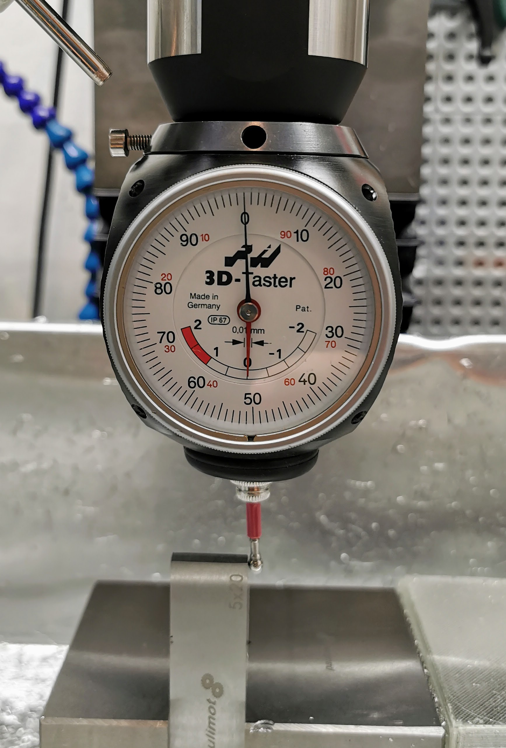
Position 2

I made this test already more times") Deviation is something under 0.01mm and not only for 180 degrees, but also for 90 and 270 degrees.
Deviation is something under 0.01mm and not only for 180 degrees, but also for 90 and 270 degrees.
Replied by Gnevko on topic Closed loop with linear encoders but still backlash?
What was your following error on the X axis at both those points? The PID may need more tuning.
Position 1
Position 2
2nd how much do you trust your edge finder gauge? It might be informative to find one side of an edge, then turn the spindle 180 degrees and check the gauge again.
I made this test already more times
Deviation is something under 0.01mm and not only for 180 degrees, but also for 90 and 270 degrees. Attachments:
Please Log in or Create an account to join the conversation.
- Todd Zuercher
-
- Away
- Platinum Member
-
Less
More
- Posts: 4742
- Thank you received: 1454
23 Jan 2020 21:28 #155576
by Todd Zuercher
Replied by Todd Zuercher on topic Closed loop with linear encoders but still backlash?
Make sure you don't have backlash compensation enabled.
Double check your encoder scale is correct.
It looks like your stepgen position feedback is closer to correct than your linear scale.
Can you measure some other sizes to see if the error is static or linear or something else? (Does the error get twice as large for double the length or is it the same?)
Please Log in or Create an account to join the conversation.
- Gnevko
- Offline
- Senior Member
-
Less
More
- Posts: 59
- Thank you received: 10
24 Jan 2020 06:34 - 24 Jan 2020 06:37 #155633
by Gnevko
I have BACKLASH = 0 in the config ini file for the X and Y joints.
The encoders have 0.001 resolution, 1000 counts per 1 mm and it seams to be correct.
It looks like your stepgen position feedback is closer to correct than your linear scale.

and as you can see, the error is the same, not double.
Some additional observation: I know that the machine has physically ca 0.06 mm backlash. I move an axis with MPG (0,01 mm steps) in one direction and can see that the value on edge finder gauge also change. Then I reverse the direction of moving and ... encoder.counter value reacts immediately on it but the value on edge finder gauge - not (ca first three steps). But how it could be? If I move the encoder per hand it reacts also linuxcnc really reads the correct value from it.
Replied by Gnevko on topic Closed loop with linear encoders but still backlash?
Make sure you don't have backlash compensation enabled.
I have BACKLASH = 0 in the config ini file for the X and Y joints.
Double check your encoder scale is correct.
The encoders have 0.001 resolution, 1000 counts per 1 mm and it seams to be correct.
It looks like your stepgen position feedback is closer to correct than your linear scale.
Of course I checked it too: just added second 20.00mm parallel:Can you measure some other sizes to see if the error is static or linear or something else? (Does the error get twice as large for double the length or is it the same?)
and as you can see, the error is the same, not double.
Some additional observation: I know that the machine has physically ca 0.06 mm backlash. I move an axis with MPG (0,01 mm steps) in one direction and can see that the value on edge finder gauge also change. Then I reverse the direction of moving and ... encoder.counter value reacts immediately on it but the value on edge finder gauge - not (ca first three steps). But how it could be? If I move the encoder per hand it reacts also linuxcnc really reads the correct value from it.
Attachments:
Last edit: 24 Jan 2020 06:37 by Gnevko.
Please Log in or Create an account to join the conversation.
- PCW
-
- Offline
- Moderator
-
Less
More
- Posts: 17917
- Thank you received: 5246
24 Jan 2020 15:14 #155652
by PCW
Replied by PCW on topic Closed loop with linear encoders but still backlash?
Can you measure the motion near the encoder?
it sounds like lost motion in the linear mechanics
(loose gibs etc)
it sounds like lost motion in the linear mechanics
(loose gibs etc)
The following user(s) said Thank You: Gnevko
Please Log in or Create an account to join the conversation.
- Todd Zuercher
-
- Away
- Platinum Member
-
Less
More
- Posts: 4742
- Thank you received: 1454
24 Jan 2020 15:16 #155653
by Todd Zuercher
Replied by Todd Zuercher on topic Closed loop with linear encoders but still backlash?
Well that seems to point at a problem with the ways, like Peter mentioned. Somehow the table is moving (twisting, tilting) in such a way that your movement at the piece is not the same as the movement at your linear scale.
The following user(s) said Thank You: Gnevko
Please Log in or Create an account to join the conversation.
- Gnevko
- Offline
- Senior Member
-
Less
More
- Posts: 59
- Thank you received: 10
26 Jan 2020 11:08 #155785
by Gnevko
Replied by Gnevko on topic Closed loop with linear encoders but still backlash?
At first - thank you, guys, for the trying to help! Yesterday I spend a lot of time and check all possible mechanical parts, but without susses, It seams that mechanics work correctly. But ok, if mechanics are ok, than I need to search the problem by the edge finder gauge. One more tests with the following results:
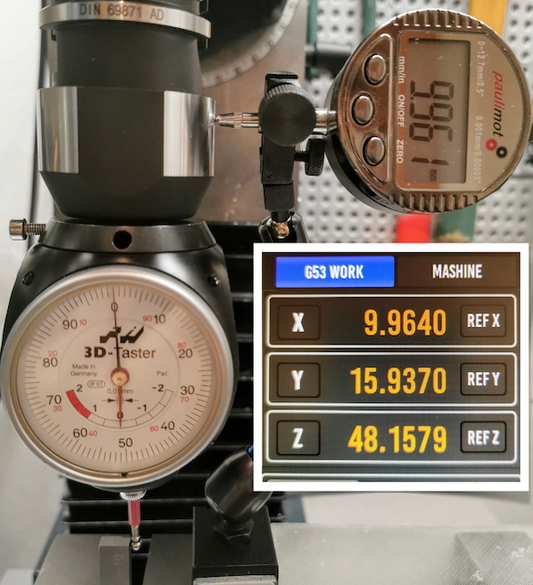
As you can see I used 10.01mm parallel, because my digital gauge can only 12,5 mm. At first I found Zero Point on the left side, set the machine and digital gauge also to Zero, and as usual tried to measure the parallel from right side. And ... the result on the digital gauge is the same (deviation is only 0.003 what it pretty cool) as the linuxcnc displays and it has the same error as by other tests with 20mm parallels.
As you can see I used 10.01mm parallel, because my digital gauge can only 12,5 mm. At first I found Zero Point on the left side, set the machine and digital gauge also to Zero, and as usual tried to measure the parallel from right side. And ... the result on the digital gauge is the same (deviation is only 0.003 what it pretty cool) as the linuxcnc displays and it has the same error as by other tests with 20mm parallels.
Attachments:
Please Log in or Create an account to join the conversation.
Time to create page: 0.322 seconds