Need some wiring help with board...
- Catch22
-
 Topic Author
- Offline
- Elite Member
-

Less
More
- Posts: 222
- Thank you received: 17
07 Apr 2020 18:31 - 07 Apr 2020 18:34 #163082
by Catch22
Need some wiring help with board... was created by Catch22
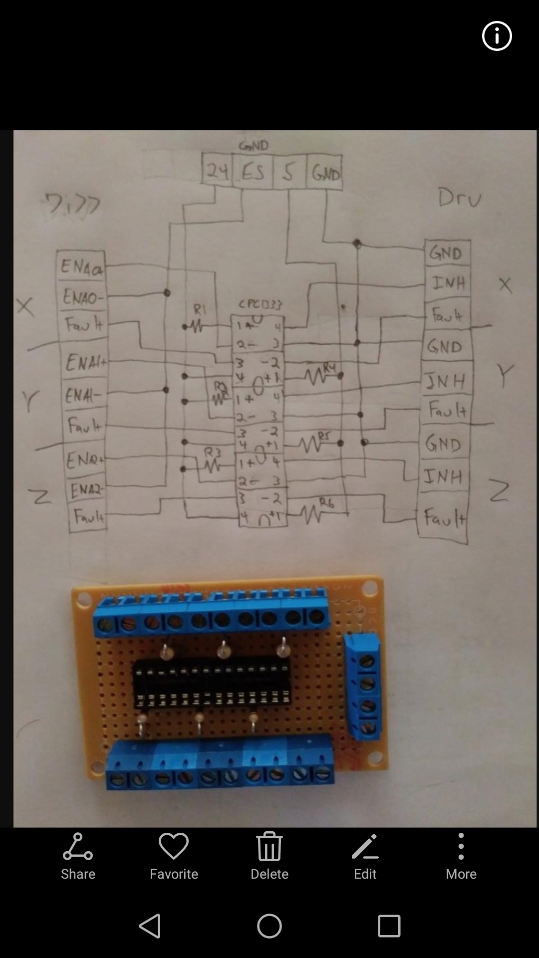
Ok so I got this board info. from a nice guy that shared it with me, but I haven't been able to get ahold of him as I have a couple of questions, I'm hoping that someone here can help me out as I'm wanting to get this done. I have attached a picture with a diagram of the board I made, there is a 24v, estop,5v and a ground, my question is do I wire the +24v into where it says 24v and the -24 into the ground, same with the estop and 5v and tie all the grounds together?
Attachments:
Last edit: 07 Apr 2020 18:34 by Catch22. Reason: Spelling mistake
Please Log in or Create an account to join the conversation.
- Catch22
-
Topic Author
- Offline
- Elite Member
-
Less
More
- Posts: 222
- Thank you received: 17
08 Apr 2020 21:43 #163245
by Catch22
Replied by Catch22 on topic Need some wiring help with board...
Can anyone help me out with this please.
Thanks Mike
Thanks Mike
Please Log in or Create an account to join the conversation.
- BeagleBrainz
-

- Visitor
-

08 Apr 2020 21:57 #163247
by BeagleBrainz
Replied by BeagleBrainz on topic Need some wiring help with board...
It would help if you provided a link to the component in the middle......the part number is a little hard to read. At the moment it's just a "black box".
But if it is an opto isolator type component you want to keep the 24v & 5v gnds separate otherwise you lose the isolation.
Are you using a 24v PSU that has +24v & -24v rails ? Or are you confusing -24v with the 24v GND ?
But if it is an opto isolator type component you want to keep the 24v & 5v gnds separate otherwise you lose the isolation.
Are you using a 24v PSU that has +24v & -24v rails ? Or are you confusing -24v with the 24v GND ?
Please Log in or Create an account to join the conversation.
- Catch22
-
Topic Author
- Offline
- Elite Member
-
Less
More
- Posts: 222
- Thank you received: 17
08 Apr 2020 22:28 - 08 Apr 2020 22:44 #163248
by Catch22
Replied by Catch22 on topic Need some wiring help with board...
Sorry they are cpc1333g ixys solid state relays, and the 24v with a ground, and how do I keep the 24v and 5v grounds separate, by using a ground on the panel for one of them?
www.google.com/url?sa=t&source=web&rct=j...&cshid=1586385823215
www.google.com/url?sa=t&source=web&rct=j...&cshid=1586385823215
Last edit: 08 Apr 2020 22:44 by Catch22.
Please Log in or Create an account to join the conversation.
- BeagleBrainz
-
- Visitor
-
08 Apr 2020 23:34 #163251
by BeagleBrainz
Replied by BeagleBrainz on topic Need some wiring help with board...
With my 7i76 I used separate power supplies.
One for 12v Field I\O that may get upgraded to 24v
One for 5v for my 7i92 & 7i76 combo
And another 5v for anything 5v devices I need power and don't connected to the Mesa 5v rails.
And of course a 48v PSU for steppers
One question, what model of driver are you using ?
One for 12v Field I\O that may get upgraded to 24v
One for 5v for my 7i92 & 7i76 combo
And another 5v for anything 5v devices I need power and don't connected to the Mesa 5v rails.
And of course a 48v PSU for steppers
One question, what model of driver are you using ?
Please Log in or Create an account to join the conversation.
- Catch22
-
Topic Author
- Offline
- Elite Member
-
Less
More
- Posts: 222
- Thank you received: 17
08 Apr 2020 23:42 #163253
by Catch22
Replied by Catch22 on topic Need some wiring help with board...
AMC BE25A20 drives. So this board is made to turn the drives on. I have a 24v power supply that is only on the Mesa 7i77 for field power, so I will come off of that for 24v and I was going to pull 5v off of the 7i77 board. The guy that made this board I haven't been able to get ahold of so I just need to know where to put the ground wires.
Please Log in or Create an account to join the conversation.
- superlen
- Offline
- Junior Member
-

Less
More
- Posts: 33
- Thank you received: 8
09 Apr 2020 00:53 #163263
by superlen
Replied by superlen on topic Need some wiring help with board...
Here is a universal quad opto board I just designed to take 422 in & drive 24V out, such as from a Mesa differential output to 24v Drive enables on Servo drives. ( should have bare boards back this week! ") )
)
- Each input can be active high, active low, or differential.
- The output is NPN to ground.
- The Input voltage and output voltage are or course independent of each other.
- Speed is about 100khz due to limitations with the opto. For simple IO, not a problem.
I've included a pic of the board showing the traces and a clip of the schematic showing one of the channels. (Hopefully, this comes through as the preview mode is clipping some. I'll edit if not.).
The schematic you posted is similar, but using the ixys parts instead of optos. I'm not familiar with the ixys SS relays, but we use about 10K pieces/year of their IGBTs on a light dimmer we manufacture. The Ixys IGBTs are great...a bit pricey, but they handle some weird surges better than any other part in that application.
You should check the speed of the SSR if you are going to do any pwm with it (say for a 0-10v drive speed signal)
Len
)- Each input can be active high, active low, or differential.
- The output is NPN to ground.
- The Input voltage and output voltage are or course independent of each other.
- Speed is about 100khz due to limitations with the opto. For simple IO, not a problem.
I've included a pic of the board showing the traces and a clip of the schematic showing one of the channels. (Hopefully, this comes through as the preview mode is clipping some. I'll edit if not.).
The schematic you posted is similar, but using the ixys parts instead of optos. I'm not familiar with the ixys SS relays, but we use about 10K pieces/year of their IGBTs on a light dimmer we manufacture. The Ixys IGBTs are great...a bit pricey, but they handle some weird surges better than any other part in that application.
You should check the speed of the SSR if you are going to do any pwm with it (say for a 0-10v drive speed signal)
Len
The following user(s) said Thank You: Catch22
Please Log in or Create an account to join the conversation.
- BeagleBrainz
-
- Visitor
-
09 Apr 2020 00:59 #163266
by BeagleBrainz
Replied by BeagleBrainz on topic Need some wiring help with board...
Nice kit, but it really doesn't help old mate with his placement of the GNDs.
Maybe PCW can chime in and help.......I can't work out how to describe the connections as to me it seems pretty straight forward.
Maybe PCW can chime in and help.......I can't work out how to describe the connections as to me it seems pretty straight forward.
Please Log in or Create an account to join the conversation.
- superlen
- Offline
- Junior Member
-
Less
More
- Posts: 33
- Thank you received: 8
09 Apr 2020 01:01 #163267
by superlen
Replied by superlen on topic Need some wiring help with board...
Like Beagle, I'm using separate power supplies (+24 and +5) & I keep the grounds segregated throughout the system. This provides the isolation which is great for noise and 'Events' that could take out a card. However, if you had to, you could tie your gnds together. You would lose the proper isolation, but the level shifting that the SSRs are going to accomplish for you would still work fine.
I'll try and get some time to digest the circuit you posted.
Len
I'll try and get some time to digest the circuit you posted.
Len
The following user(s) said Thank You: Catch22, BeagleBrainz
Please Log in or Create an account to join the conversation.
- tommylight
-

- Offline
- Moderator
-

Less
More
- Posts: 21613
- Thank you received: 7382
09 Apr 2020 01:20 #163272
by tommylight
Replied by tommylight on topic Need some wiring help with board...
I did try to help you on the other thread when you asked for the same thing.
It is not needed, everything can be wired and work without it.
Do the drives use 5 or 24V for signalling ?
If they use 24V, you can wire the fault signal directly to 7i77 inputs, it already has enable outputs, fully isolated.
If 5V, you can still wire them directly to the first 4 inputs on the 7i77, set the board to mode 2 and add some hal logic to trigger when that input reaches 5V.
The following user(s) said Thank You: Catch22, BeagleBrainz
Please Log in or Create an account to join the conversation.
Moderators: PCW, jmelson
Time to create page: 0.240 seconds