Need some wiring help with board...
- superlen
- Offline
- Junior Member
-

Less
More
- Posts: 33
- Thank you received: 8
09 Apr 2020 01:31 - 09 Apr 2020 01:35 #163274
by superlen
Replied by superlen on topic Need some wiring help with board...
Ok,
After looking at the schematic, I think there are a few things I would change. (given some Assumptions I'm about to make.") )
)
- A1 Your Estop is making a connection to gnd. So when you hit estop, gnd drops out and your enables feeding your drives need to go away.
- A2 - the Mesa is putting out differential for drive enables.
- The drive side is looking for active high (24v and they are enabled, gnd - they are disabled )
- The +24v on your connector is feeding Pin1 through a Resistor for the Mesa->Drive Enable. It would feed these by the same 5V that feeds the Mesa, not the 24v. The gnd for the ESTOP should be the same gnd as the 5v and the Mesas. When you hit ESTOP you lose your ground reference and the SSRs turn off.
It would work with the +24v as you have drawn, but this would require you to tie the Mesa gnd and the 24v gnd together so they have the same reference.... then you lose isolation.
- The GND you show on the right side of connector (call it pin4) should be your 24v gnd.
- Your INHs may need pullups to +24v.
- The 5V on the connector pin3 should be 24V (assuming fault signal from Drive is active low).
- I'm not up to speed on the fault input level requirements on the 7I77, but assuming it's 5v logic, so the pin4 of the SSRs that are feeding the faults needs to be referenced to the Mesa gnd.
The above is basically me trying to make your schematic an isolated design similar to the one I posted, and would be how I would tackle it. I'm sure I overlooked some stuff, but at least there are some ideas for people to digest/challenge.
Len
After looking at the schematic, I think there are a few things I would change. (given some Assumptions I'm about to make.
)- A1 Your Estop is making a connection to gnd. So when you hit estop, gnd drops out and your enables feeding your drives need to go away.
- A2 - the Mesa is putting out differential for drive enables.
- The drive side is looking for active high (24v and they are enabled, gnd - they are disabled )
- The +24v on your connector is feeding Pin1 through a Resistor for the Mesa->Drive Enable. It would feed these by the same 5V that feeds the Mesa, not the 24v. The gnd for the ESTOP should be the same gnd as the 5v and the Mesas. When you hit ESTOP you lose your ground reference and the SSRs turn off.
It would work with the +24v as you have drawn, but this would require you to tie the Mesa gnd and the 24v gnd together so they have the same reference.... then you lose isolation.
- The GND you show on the right side of connector (call it pin4) should be your 24v gnd.
- Your INHs may need pullups to +24v.
- The 5V on the connector pin3 should be 24V (assuming fault signal from Drive is active low).
- I'm not up to speed on the fault input level requirements on the 7I77, but assuming it's 5v logic, so the pin4 of the SSRs that are feeding the faults needs to be referenced to the Mesa gnd.
The above is basically me trying to make your schematic an isolated design similar to the one I posted, and would be how I would tackle it. I'm sure I overlooked some stuff, but at least there are some ideas for people to digest/challenge.
Len
Last edit: 09 Apr 2020 01:35 by superlen.
The following user(s) said Thank You: Catch22
Please Log in or Create an account to join the conversation.
- Catch22
-
 Topic Author
- Offline
- Elite Member
-

Less
More
- Posts: 222
- Thank you received: 17
09 Apr 2020 02:10 #163282
by Catch22
Replied by Catch22 on topic Need some wiring help with board...
I did try to help you on the other thread when you asked for the same thing.
It is not needed, everything can be wired and work without it.
Do the drives use 5 or 24V for signalling ?
If they use 24V, you can wire the fault signal directly to 7i77 inputs, it already has enable outputs, fully isolated.
If 5V, you can still wire them directly to the first 4 inputs on the 7i77, set the board to mode 2 and add some hal logic to trigger when that input reaches 5V.[/quote
I'm sorry about that tommylight, I totally forgot about you telling me that, I'm not the sharpest nice in the drawer sometimes, as for the signalling voltage I'm not really sure, I read the documents and I would say it's 5v but not 100 % here is a couple pictures of the specs.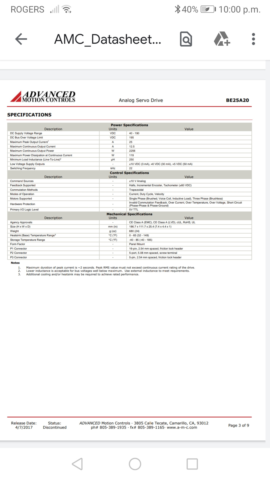
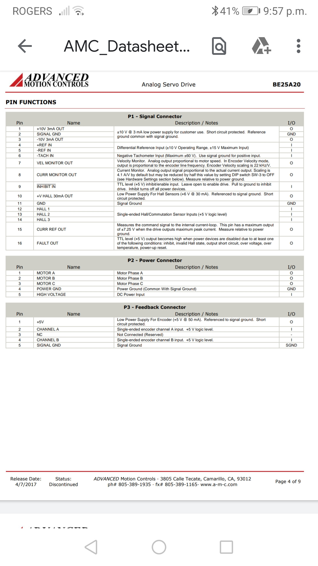
Attachments:
Please Log in or Create an account to join the conversation.
- superlen
- Offline
- Junior Member
-
Less
More
- Posts: 33
- Thank you received: 8
09 Apr 2020 02:31 - 09 Apr 2020 02:33 #163288
by superlen
Replied by superlen on topic Need some wiring help with board...
Yossarian,
Yes, you are correct. The enables and fault output are all 5v. You don't need a 24V supply in there. I gather that's probably what John was telling you in the other thread.
Len
Yes, you are correct. The enables and fault output are all 5v. You don't need a 24V supply in there. I gather that's probably what John was telling you in the other thread.
Len
Last edit: 09 Apr 2020 02:33 by superlen.
The following user(s) said Thank You: Catch22
Please Log in or Create an account to join the conversation.
- Catch22
-
Topic Author
- Offline
- Elite Member
-
Less
More
- Posts: 222
- Thank you received: 17
09 Apr 2020 02:44 #163290
by Catch22
Replied by Catch22 on topic Need some wiring help with board...
If 5V, you can still wire them directly to the first 4 inputs on the 7i77, set the board to mode 2 and add some hal logic to trigger when that input reaches 5V.
This sounds way over my head.
Where would I start looking to find out how to do this?
This sounds way over my head.
Where would I start looking to find out how to do this?
Please Log in or Create an account to join the conversation.
- tommylight
-

- Away
- Moderator
-

Less
More
- Posts: 21627
- Thank you received: 7384
09 Apr 2020 23:15 #163402
by tommylight
Replied by tommylight on topic Need some wiring help with board...
Those drives have one major issue that needs to be fixed before proceeding any further, namely the inhibit input is reversed, meaning if left unconnected the drives will be enabled, and that is a big NO for servo drives.
That can be foxed by adding a resistor to pull that input low always until Linuxcnc takes control and sends the required 5V for enabling the drives. A 1KOhm resistor should do the trick, but you will have to test that and be sure that the drives remain disabled until the enable on Linuxcnc is turned on. That input then must be connected to enable on the 7i77 for all drives separately, and the other side of the 7i77 enable connected to 5V.
The fault can be connected directly to one of the first 4 inputs on the 7i77, namely the input 0, 1, 2, 3, and those inputs should go through a comp as to trigger the fault for each axis when the input value reaches 5V, not hard to do in hal once you get the hang of it.
Do not proceed without testing the resistor part, having enable working correctly on servo driven machines is a must, there is no way around it.
Please Log in or Create an account to join the conversation.
- Catch22
-
Topic Author
- Offline
- Elite Member
-
Less
More
- Posts: 222
- Thank you received: 17
09 Apr 2020 23:26 #163405
by Catch22
Replied by Catch22 on topic Need some wiring help with board...
Ok great, so do I connect the resistor to the inhibit in to the signal ground on the drive?
Please Log in or Create an account to join the conversation.
- tommylight
-
- Away
- Moderator
-
Less
More
- Posts: 21627
- Thank you received: 7384
10 Apr 2020 00:25 #163418
by tommylight
Replied by tommylight on topic Need some wiring help with board...
Yes, inhibit it and the other side of the resistor to signal GND.Ok great, so do I connect the resistor to the inhibit in to the signal ground on the drive?
Please Log in or Create an account to join the conversation.
- BeagleBrainz
-

- Visitor
-

10 Apr 2020 00:34 #163422
by BeagleBrainz
Replied by BeagleBrainz on topic Need some wiring help with board...
Your understanding of signals and grounds seems to be a but confused as you appear to be asking where to connect grounds to.
Say I two device X & Y
Each Device is Powered by a separate power supply, say X is powered by switch mode powersupply and Y is powered by a battery.
Device X has 2 terminals X_Out and X_Gnd.
Device Y has 2 terminals Y_In and Y_Gnd.
To connect Device X to Device Y:
Term X_Out ===> Y_In
Term X_Gnd ===> Y_Gnd
Without Y_Gnd & X_Gnd being connected no signal will be seen.
Now X_Gnd & Y_Gnd are common. Theoretically if Y_In needed a pull down resistor it doesn't matter if the resistor connects to X_In & X_Gnd or Y_In or Y_Gnd. Even X_in & Y_Gnd are valid. As X_In & Y_In are connected electrically and X_Gnd & Y_Gnd are also connected electrically.
Please Log in or Create an account to join the conversation.
- Catch22
-
Topic Author
- Offline
- Elite Member
-
Less
More
- Posts: 222
- Thank you received: 17
10 Apr 2020 00:39 #163428
by Catch22
Replied by Catch22 on topic Need some wiring help with board...
Awesome, thanks I will do that tomorrow.
Please Log in or Create an account to join the conversation.
- jj80909
- Offline
- New Member
-

Less
More
- Posts: 13
- Thank you received: 3
10 Apr 2020 01:32 #163431
by jj80909
Replied by jj80909 on topic Need some wiring help with board...
For AMC (Advanced Motion Controls) servo amps, you can easily invert the inhibit signal by removing a shunt soldered to the amplifier board (J1).
With J1 removed, you can wire directly to the Mesa enable - no relay(s) needed.
Jim
With J1 removed, you can wire directly to the Mesa enable - no relay(s) needed.
Jim
The following user(s) said Thank You: Catch22
Please Log in or Create an account to join the conversation.
Moderators: PCW, jmelson
Time to create page: 0.344 seconds