Need some wiring help with board...

More
6 years 6 months ago #163263 by superlen
Here is a universal quad opto board I just designed to take 422 in & drive 24V out, such as from a Mesa differential output to 24v Drive enables on Servo drives. ( should have bare boards back this week! :) )

- Each input can be active high, active low, or differential.
- The output is NPN to ground.
- The Input voltage and output voltage are or course independent of each other.
- Speed is about 100khz due to limitations with the opto. For simple IO, not a problem.

I've included a pic of the board showing the traces and a clip of the schematic showing one of the channels. (Hopefully, this comes through as the preview mode is clipping some. I'll edit if not.).

The schematic you posted is similar, but using the ixys parts instead of optos. I'm not familiar with the ixys SS relays, but we use about 10K pieces/year of their IGBTs on a light dimmer we manufacture. The Ixys IGBTs are great...a bit pricey, but they handle some weird surges better than any other part in that application.

You should check the speed of the SSR if you are going to do any pwm with it (say for a 0-10v drive speed signal)

Len
The following user(s) said Thank You: Catch22

Please Log in or Create an account to join the conversation.

  • BeagleBrainz
  • New Member
  • New Member
More
6 years 6 months ago #163266 by BeagleBrainz
Replied by BeagleBrainz on topic Need some wiring help with board...
Nice kit, but it really doesn't help old mate with his placement of the GNDs.

Maybe PCW can chime in and help.......I can't work out how to describe the connections as to me it seems pretty straight forward.

Please Log in or Create an account to join the conversation.

More
6 years 6 months ago #163267 by superlen
Like Beagle, I'm using separate power supplies (+24 and +5) & I keep the grounds segregated throughout the system. This provides the isolation which is great for noise and 'Events' that could take out a card. However, if you had to, you could tie your gnds together. You would lose the proper isolation, but the level shifting that the SSRs are going to accomplish for you would still work fine.

I'll try and get some time to digest the circuit you posted.

Len
The following user(s) said Thank You: Catch22, BeagleBrainz

Please Log in or Create an account to join the conversation.

More
6 years 6 months ago #163272 by tommylight
I did try to help you on the other thread when you asked for the same thing.
It is not needed, everything can be wired and work without it.
Do the drives use 5 or 24V for signalling ?
If they use 24V, you can wire the fault signal directly to 7i77 inputs, it already has enable outputs, fully isolated.
If 5V, you can still wire them directly to the first 4 inputs on the 7i77, set the board to mode 2 and add some hal logic to trigger when that input reaches 5V.
The following user(s) said Thank You: Catch22, BeagleBrainz

Please Log in or Create an account to join the conversation.

More
6 years 6 months ago - 6 years 6 months ago #163274 by superlen
Ok,

After looking at the schematic, I think there are a few things I would change. (given some Assumptions I'm about to make. :) )

- A1 Your Estop is making a connection to gnd. So when you hit estop, gnd drops out and your enables feeding your drives need to go away.
- A2 - the Mesa is putting out differential for drive enables.
- The drive side is looking for active high (24v and they are enabled, gnd - they are disabled )
- The +24v on your connector is feeding Pin1 through a Resistor for the Mesa->Drive Enable. It would feed these by the same 5V that feeds the Mesa, not the 24v. The gnd for the ESTOP should be the same gnd as the 5v and the Mesas. When you hit ESTOP you lose your ground reference and the SSRs turn off.
It would work with the +24v as you have drawn, but this would require you to tie the Mesa gnd and the 24v gnd together so they have the same reference.... then you lose isolation.

- The GND you show on the right side of connector (call it pin4) should be your 24v gnd.
- Your INHs may need pullups to +24v.
- The 5V on the connector pin3 should be 24V (assuming fault signal from Drive is active low).
- I'm not up to speed on the fault input level requirements on the 7I77, but assuming it's 5v logic, so the pin4 of the SSRs that are feeding the faults needs to be referenced to the Mesa gnd.

The above is basically me trying to make your schematic an isolated design similar to the one I posted, and would be how I would tackle it. I'm sure I overlooked some stuff, but at least there are some ideas for people to digest/challenge.

Len
Last edit: 6 years 6 months ago by superlen.
The following user(s) said Thank You: Catch22, BeagleBrainz

Please Log in or Create an account to join the conversation.

More
6 years 6 months ago #163282 by Catch22

tommylight wrote: I did try to help you on the other thread when you asked for the same thing.
It is not needed, everything can be wired and work without it.
Do the drives use 5 or 24V for signalling ?
If they use 24V, you can wire the fault signal directly to 7i77 inputs, it already has enable outputs, fully isolated.
If 5V, you can still wire them directly to the first 4 inputs on the 7i77, set the board to mode 2 and add some hal logic to trigger when that input reaches 5V.[/quote


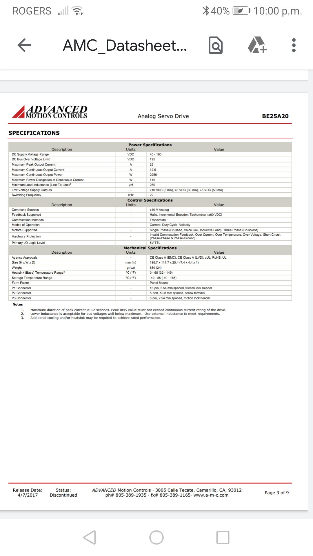
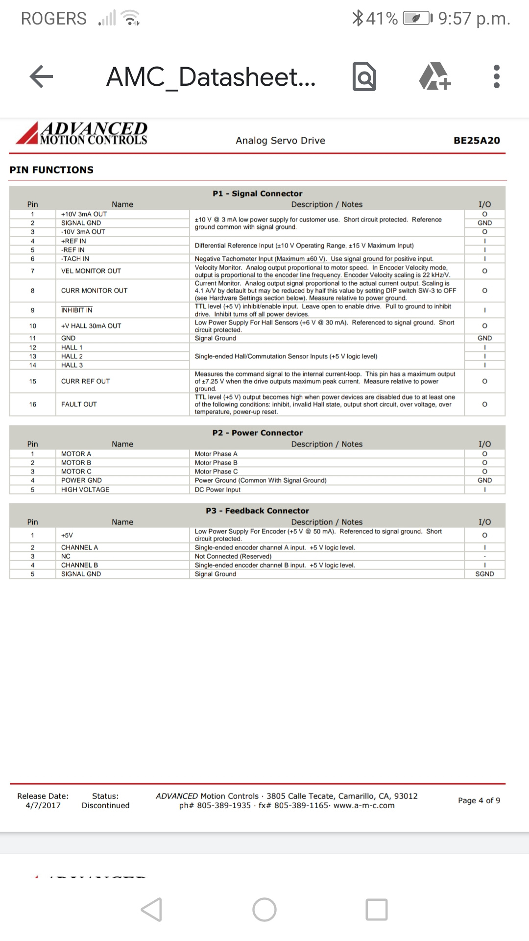
I'm sorry about that tommylight, I totally forgot about you telling me that, I'm not the sharpest nice in the drawer sometimes, as for the signalling voltage I'm not really sure, I read the documents and I would say it's 5v but not 100 % here is a couple pictures of the specs.
Please Log in or Create an account to join the conversation.

Moderators: PCW, jmelson
Time to create page: 0.464 seconds
Powered by Kunena Forum
