7i97 hookup help
- PCW
-

- Away
- Moderator
-

Less
More
- Posts: 17946
- Thank you received: 5257
08 Jul 2022 13:14 #246858
by PCW
Replied by PCW on topic 7i97 hookup help
By pulldown resistor I mean an external resistor from the drives inhibit input
to ground. This should disable the drive unless the inhibit input is pulled up
by the enable output or SSR output.
You would need to measure the open circuit voltage (no pulldown resistor)
on the inhibit input to determine the required pullup voltage.
Connections:
V+ --> SSR+
SSR- --> drive inhibit input
Resistor_pin1 --> drive inhibit input
Resisior_pin2 --> drive ground
V+ determined by open circuit inhibit voltage
By SSR I mean one of the 7I97s 6 built in SSRs
Please Log in or Create an account to join the conversation.
- Kylizer
- Offline
- Premium Member
-

Less
More
- Posts: 99
- Thank you received: 1
12 Jul 2022 15:03 #247153
by Kylizer
Replied by Kylizer on topic 7i97 hookup help
Is any of this looking right so far? Some guidence would be appreciated

Attachments:
Please Log in or Create an account to join the conversation.
- PCW
-
- Away
- Moderator
-
Less
More
- Posts: 17946
- Thank you received: 5257
12 Jul 2022 15:16 #247155
by PCW
Replied by PCW on topic 7i97 hookup help
No, there is no power supply involved on the inhibit side
(If grounding the inhibit line disables the drives)
Relay NC ---> Drive Inhibit
Relay COM -->Drive GND
(If grounding the inhibit line disables the drives)
Relay NC ---> Drive Inhibit
Relay COM -->Drive GND
Please Log in or Create an account to join the conversation.
- JPL
- Offline
- Platinum Member
-

Less
More
- Posts: 337
- Thank you received: 118
12 Jul 2022 16:37 #247162
by JPL
Replied by JPL on topic 7i97 hookup help
And you're are basically shorting your power supply by doing it this way

See: The NC and COM contact from your relay are normally closed (eg. connected together inside the relay) . The full circuit you have is: 12V+ --> Relay NC --> Relay COM --> ground. This is doing the very same as connecting directly the 12v+ to ground (Pouf!!!)... Unless, of course, the relay is being kept activated. (Then Pouf!!! once the relay is deactivated)
See: The NC and COM contact from your relay are normally closed (eg. connected together inside the relay) . The full circuit you have is: 12V+ --> Relay NC --> Relay COM --> ground. This is doing the very same as connecting directly the 12v+ to ground (Pouf!!!)... Unless, of course, the relay is being kept activated. (Then Pouf!!! once the relay is deactivated)
The following user(s) said Thank You: tommylight
Please Log in or Create an account to join the conversation.
- Kylizer
- Offline
- Premium Member
-
Less
More
- Posts: 99
- Thank you received: 1
12 Jul 2022 17:03 #247165
by Kylizer
Replied by Kylizer on topic 7i97 hookup help
Like this?
Attachments:
Please Log in or Create an account to join the conversation.
- PCW
-
- Away
- Moderator
-
Less
More
- Posts: 17946
- Thank you received: 5257
12 Jul 2022 17:17 - 12 Jul 2022 17:19 #247168
by PCW
Replied by PCW on topic 7i97 hookup help
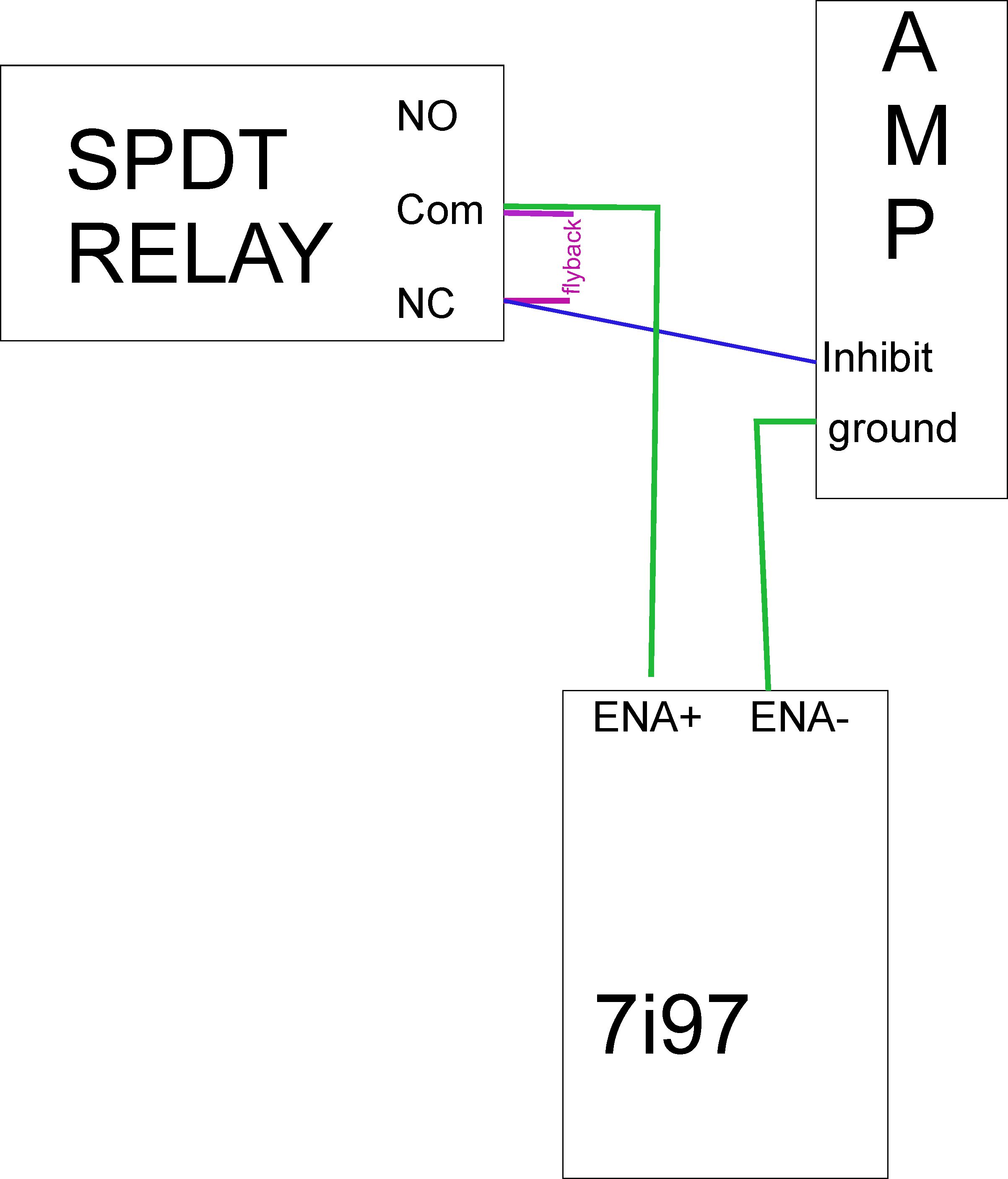
No, the relay NC and COM contacts connect to
the drives inhibit and GND and no flyback diode is used there.
There is no connection at all from the drive to the ENA lines,
the ENA lines are used to drive the relay coil (the relay coil has the flyback installed)
I will try and draw a simple schematic later today
the drives inhibit and GND and no flyback diode is used there.
There is no connection at all from the drive to the ENA lines,
the ENA lines are used to drive the relay coil (the relay coil has the flyback installed)
I will try and draw a simple schematic later today
Last edit: 12 Jul 2022 17:19 by PCW.
Please Log in or Create an account to join the conversation.
- PCW
-
- Away
- Moderator
-
Less
More
- Posts: 17946
- Thank you received: 5257
12 Jul 2022 20:02 - 12 Jul 2022 22:53 #247178
by PCW
Replied by PCW on topic 7i97 hookup help
Note that diode polarity is critical (band to +12V) , you will damage the 7I97 if it is installed backwards
Note that the relay pin numbers are meaningless unless you are using an identical relay
Note that the relay pin numbers are meaningless unless you are using an identical relay
Attachments:
Last edit: 12 Jul 2022 22:53 by PCW.
Please Log in or Create an account to join the conversation.
- Kylizer
- Offline
- Premium Member
-
Less
More
- Posts: 99
- Thank you received: 1
13 Jul 2022 13:08 #247233
by Kylizer
Replied by Kylizer on topic 7i97 hookup help
Can that relay be a SPDT? Also I’m not familiar with electrical symbols and was wondering where it’s showing to hook to on the relay. NC, NO, and Common. This is what’s on my SPDT relays anyway. If this won’t work I will purchase the DPDT
Please Log in or Create an account to join the conversation.
- Clive S
- Offline
- Platinum Member
-
Less
More
- Posts: 2204
- Thank you received: 486
13 Jul 2022 14:17 #247237
by Clive S
Yes no problem. If you look at PCW's schematic although he shows a DPDT he is using it as a SPDT ie. only using one set of contacts
Replied by Clive S on topic 7i97 hookup help
Can that relay be a SPDT? Also I’m not familiar with electrical symbols and was wondering where it’s showing to hook to on the relay. NC, NO, and Common. This is what’s on my SPDT relays anyway. If this won’t work I will purchase the DPDT
Yes no problem. If you look at PCW's schematic although he shows a DPDT he is using it as a SPDT ie. only using one set of contacts
The following user(s) said Thank You: Kylizer
Please Log in or Create an account to join the conversation.
- JPL
- Offline
- Platinum Member
-
Less
More
- Posts: 337
- Thank you received: 118
13 Jul 2022 17:48 #247245
by JPL
For any relay you will have 2 sides:.
One side is the contacts side with the marking NC, NO and C (common). This is the controlled side that is acting like a switch, The Common is contact #2 of PCW drawing. When the relay is not activated this contact is (internally) connected to the NC contact. When the relay is activated the small 'lever' that was connecting C to NC change direction and will now internally connect C to NO (while disconnecting C to NC)
If you look again at PCW drawing you will then see that there's 2 possible paths:
If the relay is NOT activated (as shown on the drawing): Signal comes from "Drive inhibit" goes to contact NC (#3) then it is internally connected to the COMmon of the relay (contact #2), which is connected to "Drive Ground". Drive inhibit is then effectively connected to drive ground.
When the relay is activated: The internal contact is now from Common (#2) to the NO (normally open) contact #1. Which is also disconnecting Common to NC (internally). By doing this the Drive inhibit signal is effectively disconnected (from the drive ground) with nowhere to go.
The second side is the 'control" side: (this is probably the part that you're missing to understand)
For a mechanical relay this is usually a simple coil that is the equivalent of an electro magnet. When voltage is applied to it the magnet will move a small mechanical lever that will change the position of a small lever allowing it to move the connection from C -> NO to C -> NC. This is basically the same effect as manually turning a regular switch on and off.
It is IMPORTANT that the rating for the coil for the relay you are going to use is the same as the voltage controlling the relay. In this case you can see that PCW drawing have the '+12V power' connected to contact #4, while "7I97 ENA+" is connected to the other side of the coil (#5). It is then MANDATORY to use a 12V relay for this design. Be careful not to confuse the contacts rating with the coil rating. (Contacts rating are usually much higher (eg 125V) than the coil rating)
Replied by JPL on topic 7i97 hookup help
Can that relay be a SPDT? Also I’m not familiar with electrical symbols and was wondering where it’s showing to hook to on the relay. NC, NO, and Common. This is what’s on my SPDT relays anyway. If this won’t work I will purchase the DPDT
For any relay you will have 2 sides:.
One side is the contacts side with the marking NC, NO and C (common). This is the controlled side that is acting like a switch, The Common is contact #2 of PCW drawing. When the relay is not activated this contact is (internally) connected to the NC contact. When the relay is activated the small 'lever' that was connecting C to NC change direction and will now internally connect C to NO (while disconnecting C to NC)
If you look again at PCW drawing you will then see that there's 2 possible paths:
If the relay is NOT activated (as shown on the drawing): Signal comes from "Drive inhibit" goes to contact NC (#3) then it is internally connected to the COMmon of the relay (contact #2), which is connected to "Drive Ground". Drive inhibit is then effectively connected to drive ground.
When the relay is activated: The internal contact is now from Common (#2) to the NO (normally open) contact #1. Which is also disconnecting Common to NC (internally). By doing this the Drive inhibit signal is effectively disconnected (from the drive ground) with nowhere to go.
The second side is the 'control" side: (this is probably the part that you're missing to understand)
For a mechanical relay this is usually a simple coil that is the equivalent of an electro magnet. When voltage is applied to it the magnet will move a small mechanical lever that will change the position of a small lever allowing it to move the connection from C -> NO to C -> NC. This is basically the same effect as manually turning a regular switch on and off.
It is IMPORTANT that the rating for the coil for the relay you are going to use is the same as the voltage controlling the relay. In this case you can see that PCW drawing have the '+12V power' connected to contact #4, while "7I97 ENA+" is connected to the other side of the coil (#5). It is then MANDATORY to use a 12V relay for this design. Be careful not to confuse the contacts rating with the coil rating. (Contacts rating are usually much higher (eg 125V) than the coil rating)
Please Log in or Create an account to join the conversation.
Moderators: PCW, jmelson
Time to create page: 1.414 seconds