Probe Interface Board Design (resistance switching)
- fletch
-
 Topic Author
- Offline
- Premium Member
-

- Posts: 139
- Thank you received: 70
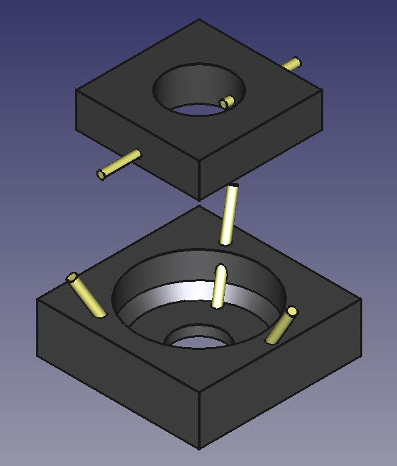
Thanks again Andy - I'll be definitely have a go at designing/making a more precise one - I like the idea of being able to repair/replace it when (not if) I crash it.
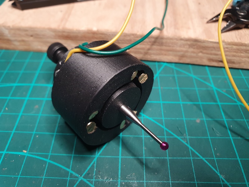
Edit: Now I've removed the chrome this now shows similar electrical characteristics as the Renishaw TP6.
Attachments:
Please Log in or Create an account to join the conversation.
- cakeslob
- Offline
- Platinum Member
-

- Posts: 923
- Thank you received: 275
Try playing with the tension thing, and back it off all the way. when i was playing with mine, i thought the tension rod had something to do with my issue, but it turned out to not work well when just using a volt meter, i needed to use 24v
The tp6 is bigger than the tp2, so it might be easier to disassemble, but for the tp2 it looks like i need to make some custom tools. i couldnt get it apart easy at all, so i stopped trying because i didnt want to break it.
Please Log in or Create an account to join the conversation.
- fletch
-
 Topic Author
- Offline
- Premium Member
-

- Posts: 139
- Thank you received: 70
The TP6 looks like the top cap should unscrew from the main body and/but there are three 'pin holes' that could either be for a specialised pin spanner
Up until it broke, the contact resistance was a bit variable (probably because of the lack of spring tension) but operated fine at 5v with the 'check if still open loop' able to detect closed at 0.5v. Now I've removed the chrome, my '3D printed special' shows similar characteristics.
Philip
Please Log in or Create an account to join the conversation.
- fletch
-
 Topic Author
- Offline
- Premium Member
-

- Posts: 139
- Thank you received: 70
Apart from an interference fit that caused a fair bit of head scratching, the process went smoothly. Some of the smallest springs I have ever seen but the culprit was the central spring knocked sideways - a complete pig to reassemble (three times) but it is done. Electrical resistance is quite high, so I suspect I'll have to have it apart again to do a proper clean up.
If anyone is interested in seeing the internals of a Renishaw, then I have a couple of photos, otherwise normal service on the interface board will be resumed.
Attachments:
Please Log in or Create an account to join the conversation.
- vre
- Offline
- Platinum Member
-

- Posts: 610
- Thank you received: 17
Knows soneone the comunication ptotocol to impement a receiver or
if it is posible mod it and use it with wired connection?
Please Log in or Create an account to join the conversation.
- dm17ry
-

- Offline
- Elite Member
-

- Posts: 193
- Thank you received: 78
i played with a few renishaw probes a while back - namely TP6, TP1s. yes, the resistance can be quite high and variable. but PI4 and MI8 interface units i had could reliably detected it. AFAIR, they supply 10 VDC at 0.5 mA to the probe. resistance less than about 3 kOhm considered as a seated probe.Up until it broke, the contact resistance was a bit variable (probably because of the lack of spring tension) but operated fine at 5v with the 'check if still open loop' able to detect closed at 0.5v. Now I've removed the chrome, my '3D printed special' shows similar characteristics.
Please Log in or Create an account to join the conversation.
- vre
- Offline
- Platinum Member
-

- Posts: 610
- Thank you received: 17
So must have mcu with a voltage comparator?
Please Log in or Create an account to join the conversation.
- fletch
-
 Topic Author
- Offline
- Premium Member
-

- Posts: 139
- Thank you received: 70
That is a very nice probe. There's a lot of information on the Renishaw site here but predicatably no information at all the protocol. Reading the IR outputs from the probe would be fairly(!) trivial with an IR reader/oscilloscope/Arduino but without the OMM receiver, the IR inputs to the probe would be challenging to say the least.I have a renishaw omp60 but i don't have the wireless ir-receiver so it is useless.
Knows soneone the comunication ptotocol to impement a receiver or
if it is posible mod it and use it with wired connection?
I suspect it would not be prudent to convert the probe to wired - there's a whole lot of electronics packed inside!
Please Log in or Create an account to join the conversation.
- fletch
-
 Topic Author
- Offline
- Premium Member
-

- Posts: 139
- Thank you received: 70
i played with a few renishaw probes a while back - namely TP6, TP1s. yes, the resistance can be quite high and variable. but PI4 and MI8 interface units i had could reliably detected it. AFAIR, they supply 10 VDC at 0.5 mA to the probe. resistance less than about 3 kOhm considered as a seated probe.
Thank you Dmitry, that is very useful information. It validates my decision to implement a Wheatstone bridge to be able to 'tune out' the probe resistance but only up to 2K atm!
I'm using 5VDC with 10K resistance (2x 20K in parallel in the bridge) which fortuitously turns out to be 0.5mA! Happy camper.
Philip
Please Log in or Create an account to join the conversation.
- dm17ry
-

- Offline
- Elite Member
-

- Posts: 193
- Thank you received: 78
The probe turns on after receiving 500Hz for 1/4 sec.. it has internal a switch for selecting auto power of or power of with the same signal that turn it on.
Once turned on, the probe sends out a 19.2K baud byte every 16 ms, and when there is a change of state of the probe tip. When not triggered, the byte is :
01010100 (with 1 meaning LED lit)
on the first transmission after the probe is deflected it sends:
11010100
after the first transmission of a trigger, it sends
10010100 as long as the probe is still deflected
The last bit goes to a 1 when the battery is low.
The start bit of the data is not shown above, it is with the
LED lit.
Please Log in or Create an account to join the conversation.


