Light Machine Corp. Benchman XTr (retrofit)
- steve_a
- Offline
- Senior Member
-

Less
More
- Posts: 75
- Thank you received: 2
15 Jun 2018 04:07 #112391
by steve_a
Replied by steve_a on topic Light Machine Corp. Benchman XTr (retrofit)
What board is that? I think I have two of those. I'm not using them and don't know if either works. I'll check and if I do you are welcome to try them.
Please Log in or Create an account to join the conversation.
- project-pegasus
-

- Visitor
-

15 Jun 2018 04:33 #112393
by project-pegasus
Replied by project-pegasus on topic Light Machine Corp. Benchman XTr (retrofit)
Wow! Thank you Steve.
Here's a photo of mine:
Is there some way to PM you here?
Here's a photo of mine:
Is there some way to PM you here?
Please Log in or Create an account to join the conversation.
- x-Intelitek Engineer
- Offline
- Premium Member
-

Less
More
- Posts: 113
- Thank you received: 22
15 Jun 2018 12:20 #112401
by x-Intelitek Engineer
Replied by x-Intelitek Engineer on topic Light Machine Corp. Benchman XTr (retrofit)
Be careful using another ATC board. Although the hardware is the same, the onboard code may be different based on the configuration of the donor machine. U4 and U14 should be the same, but U6 will be different. Check the printed label on each to verify. It is unlikely (but not impossible) your short at J8 would have damaged U4, it is powered by onboard generated +5V. If you actually did damage U4 by the short, I would suspect that a lot more than just U4 has been damaged.
If you destroyed the COM1, did you reconfigure the software to redirect ATC commands to the new COM port? Did you ever get the onboard ATC diagnostics to operate?
If you destroyed the COM1, did you reconfigure the software to redirect ATC commands to the new COM port? Did you ever get the onboard ATC diagnostics to operate?
Please Log in or Create an account to join the conversation.
- andypugh
-

- Offline
- Moderator
-

Less
More
- Posts: 19879
- Thank you received: 4643
15 Jun 2018 12:26 #112402
by andypugh
Replied by andypugh on topic Light Machine Corp. Benchman XTr (retrofit)
Is this machine running LinuxCNC? I think I would be looking to shift ATC control to LinuxCNC (so that I have hardware and software that I understand).
You can do the sequencing in G-code, so no need to learn a new language. There is an example here in one of the Vismach virtual machines:
github.com/LinuxCNC/linuxcnc/blob/master...hange/toolchange.ngc
You can do the sequencing in G-code, so no need to learn a new language. There is an example here in one of the Vismach virtual machines:
github.com/LinuxCNC/linuxcnc/blob/master...hange/toolchange.ngc
Please Log in or Create an account to join the conversation.
- steve_a
- Offline
- Senior Member
-
Less
More
- Posts: 75
- Thank you received: 2
15 Jun 2018 17:55 #112424
by steve_a
Replied by steve_a on topic Light Machine Corp. Benchman XTr (retrofit)
Bad news. I searched the shop and those boards are missing. I found two of the other boards but not the ATC boards. I can only assume they are victims of a shop clean out. Sorry to have raised your hopes without having the boards in hand.
Please Log in or Create an account to join the conversation.
- project-pegasus
-
- Visitor
-
15 Jun 2018 18:29 #112425
by project-pegasus
Replied by project-pegasus on topic Light Machine Corp. Benchman XTr (retrofit)
Bummer. But thank you, Steve for offering and looking for those. I do appreciate it.
I did reconfigure the machine to use COM2 but I haven't been able to figure out the onboard ATC diagnostics. In the schematics you posted J7 is the Host interface and shows 8 wires going back to the MU board, but mine only has two wires. Is J11 the connector for the onboard diagnostics? My pcb has the holes at J11 but no connector. I will post a picture.
The machine is not running LinuxCNC. I spent a good deal of time getting it to run on the original software with the Nextmove PC card and I would hate to see that work go to waste, but I might have to go that route in the future.
Please Log in or Create an account to join the conversation.
- project-pegasus
-
- Visitor
-
15 Jun 2018 18:43 #112427
by project-pegasus
Replied by project-pegasus on topic Light Machine Corp. Benchman XTr (retrofit)
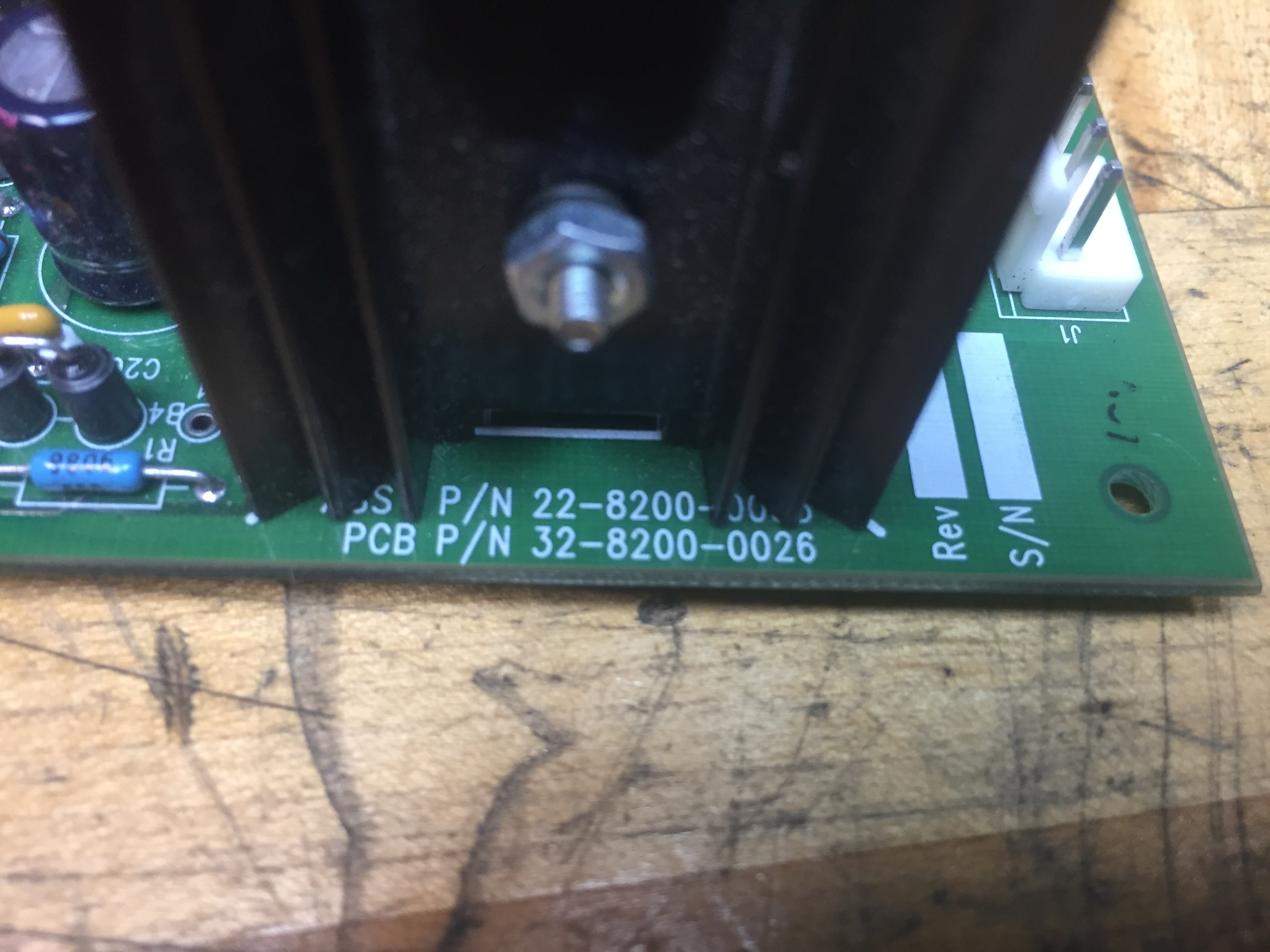
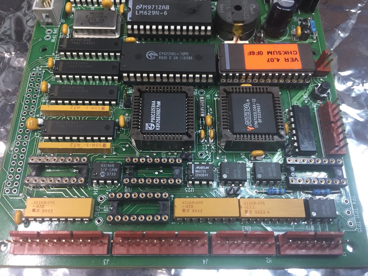
Here's my ATC board:
Please Log in or Create an account to join the conversation.
- x-Intelitek Engineer
- Offline
- Premium Member
-
Less
More
- Posts: 113
- Thank you received: 22
18 Jun 2018 16:47 #112551
by x-Intelitek Engineer
Replied by x-Intelitek Engineer on topic Light Machine Corp. Benchman XTr (retrofit)
J11 was only used for development. We never removed it for production boards.
J7 should only have 2 wires to it, Pins 1 and 8. It is used only for reset of the toolchanger.
All communications to the ATC happen through J2.
If you set up Hyperterminal,you should be able to get into the onboard diagnostics.
<ctrl> H, <alt> H, <shift> H, or maybe <alt><shift> H, I do not recall.
J7 was only a way to access U4 for programming and for the Toolchanger RESET function.
I have my data files from that time, but I do not have my notebooks.
Everything is what I can remember, but even that is suspect.
Please Log in or Create an account to join the conversation.
- project-pegasus
-
- Visitor
-
20 Jun 2018 22:22 #112672
by project-pegasus
Replied by project-pegasus on topic Light Machine Corp. Benchman XTr (retrofit)
I tried communicating with the ATC through Hyperterminal but wasn't able to get any kind of response from the machine. I hooked up an oscilloscope to the test points on the ATC board for the RS232 communication (Test Points 18, 6, and 7) and saw the square wave form. Seemed to be static for TX, not sure if it was the same byte repeating. The Max233 RS232 interface seems to be working fine, it's dropping the the waveform amplitude down to around 5V.
When I try to operate the ATC I keep getting the message "ATC send command error" and the software freezes up. What exactly does the ATC Reset button do?
When I try to operate the ATC I keep getting the message "ATC send command error" and the software freezes up. What exactly does the ATC Reset button do?
Please Log in or Create an account to join the conversation.
- x-Intelitek Engineer
- Offline
- Premium Member
-
Less
More
- Posts: 113
- Thank you received: 22
21 Jun 2018 18:47 #112736
by x-Intelitek Engineer
Replied by x-Intelitek Engineer on topic Light Machine Corp. Benchman XTr (retrofit)
The button on the board SW1 triggers the manual reset on the MAX705 IC (U25) to trigger a soft reset to U4.
Please note that J2-5 (TP6) is the data IN to the ATC and J2-3 (TP7) is the data OUT of the ATC. For some reason the schematic incorrectly has the input marked TX and the output marked RX.
Do you have +5V, are U25-7 and U25-5 both +5V?
Please note that J2-5 (TP6) is the data IN to the ATC and J2-3 (TP7) is the data OUT of the ATC. For some reason the schematic incorrectly has the input marked TX and the output marked RX.
Do you have +5V, are U25-7 and U25-5 both +5V?
Please Log in or Create an account to join the conversation.
Time to create page: 0.198 seconds