Light Machine Corp. Benchman XTr (retrofit)
- x-Intelitek Engineer
- Offline
- Premium Member
-

Less
More
- Posts: 113
- Thank you received: 22
24 Jul 2018 19:34 #114761
by x-Intelitek Engineer
Replied by x-Intelitek Engineer on topic Light Machine Corp. Benchman XTr (retrofit)
The output enables for U2 & U3 originate at U4. The Latch Enable originates at U10. I guess I missed the part where you told us that RN5 was bad. Are you troubleshooting with an oscilloscope or a meter? Hopefully an oscilloscope. When U2 pin 11 goes low, it latches internally and "captures" the status of the signals on the D pins 2-9. When U2 pin 1 goes low, that data is presented on the Q pins 12-19. you will not detect these signals with a meter, you need an oscilloscope.
Please Log in or Create an account to join the conversation.
- project-pegasus
-

- Visitor
-

25 Jul 2018 00:30 #114784
by project-pegasus
Replied by project-pegasus on topic Light Machine Corp. Benchman XTr (retrofit)
Well, I gave up trying to figure this out and sent the board into Intelitek. Hopefully they can diagnose the problem. I will let you know what they tell me. Thanks again for all the help!
Please Log in or Create an account to join the conversation.
- x-Intelitek Engineer
- Offline
- Premium Member
-
Less
More
- Posts: 113
- Thank you received: 22
30 Jul 2018 17:57 #115158
by x-Intelitek Engineer
Replied by x-Intelitek Engineer on topic Light Machine Corp. Benchman XTr (retrofit)
Please let me know what the results are.
Please Log in or Create an account to join the conversation.
- steve_a
- Offline
- Senior Member
-

Less
More
- Posts: 75
- Thank you received: 2
30 Aug 2018 04:34 #116835
by steve_a
Replied by steve_a on topic Light Machine Corp. Benchman XTr (retrofit) Spindle issue
Have a small problem. I have a wire that broke off the spindle assembly. I think it is the spindle position sensor (not using it currently but hope to in the future). It has three small wires, Black, Blue and Yellow I think. I wanted to see where it goes and rewire the unit. I COULD just splice the wires but I have only a short piece to work with on the spindle side. I want to remove the round black assembly that sits on top of the spindle and I believe it houses the pnuematics for the tool clamp. It has two air hoses. I backed out 4 long bolts that seem long enough to be the mounting bolts but the assemble did not come loose. I tried one of the other bolts but it was way too short to be a mounting bolt so I am confident I have pulled the correct ones. I tapped it pretty good with a dead blow hammer to see if it was just a waterproofing sealant that was holding it in place. Didn't budge. If I understand how the tool clamp works, I don't see what I else I would need to remove this piece. (I believe the pnuematic just pushed down on the tool clamp when activated for release and a spring clamps the tool in place when the pnuematic is deactivated so it should be totally clear to allow the spindle to move freely. ) Any hidden wisdom I might be missing?
Please Log in or Create an account to join the conversation.
- project-pegasus
-
- Visitor
-
30 Aug 2018 22:54 #116892
by project-pegasus
Replied by project-pegasus on topic Light Machine Corp. Benchman XTr (retrofit) Spindle issue
Please Log in or Create an account to join the conversation.
- steve_a
- Offline
- Senior Member
-
Less
More
- Posts: 75
- Thank you received: 2
31 Aug 2018 03:53 #116898
by steve_a
Replied by steve_a on topic Light Machine Corp. Benchman XTr (retrofit) Spindle issue
Oh WOW! Brilliant! Just what I needed! I'll include you in our Thanksgiving Day Thanks list!!!
Please Log in or Create an account to join the conversation.
- steve_a
- Offline
- Senior Member
-
Less
More
- Posts: 75
- Thank you received: 2
21 Oct 2018 04:21 #119151
by steve_a
Replied by steve_a on topic Light Machine Corp. Benchman XTr (retrofit) Spindle Sensor Question
I have repaired the spindle sensor wires. Ok I ASSUME this is the index sensor for the spindle since it is the only sensor on the spindle. It has three wires, Black, Blue and Brown. Anyone have any information on this sensor and what signals to expect or some diagram that shows how it is powered?
Thanks
Thanks
Please Log in or Create an account to join the conversation.
- tommylight
-

- Away
- Moderator
-

Less
More
- Posts: 21741
- Thank you received: 7430
21 Oct 2018 06:41 #119152
by tommylight
Replied by tommylight on topic Light Machine Corp. Benchman XTr (retrofit) Spindle Sensor Question
That should be a proximity switch and the wire colours should be standard.
Please Log in or Create an account to join the conversation.
- andypugh
-

- Offline
- Moderator
-
Less
More
- Posts: 19879
- Thank you received: 4643
21 Oct 2018 18:46 - 21 Oct 2018 18:47 #119172
by andypugh
Those are proximity switch colours.
Brown is power (typically 6 to 30 V)
Blue is 0V
Black is the output.
The black wire will either switch-to-0V for NPN switches (ie, current can flow into the black wire from a higher voltage) or switch to-live with PNP switches (so the black wire will be connected to the brown wire, and will carry the same voltage as that).
NPN is often more convenient as it allows you to operate 5V (or 3,3V) inputs even though the switches are typically powered by 24V.
However PNP works better with Mesa cards like the 7i76 which work on 24V field power.
Experiment is probably the only way to tell which type you have.
Replied by andypugh on topic Light Machine Corp. Benchman XTr (retrofit) Spindle Sensor Question
It has three wires, Black, Blue and Brown. Anyone have any information on this sensor and what signals to expect or some diagram that shows how it is powered?
Those are proximity switch colours.
Brown is power (typically 6 to 30 V)
Blue is 0V
Black is the output.
The black wire will either switch-to-0V for NPN switches (ie, current can flow into the black wire from a higher voltage) or switch to-live with PNP switches (so the black wire will be connected to the brown wire, and will carry the same voltage as that).
NPN is often more convenient as it allows you to operate 5V (or 3,3V) inputs even though the switches are typically powered by 24V.
However PNP works better with Mesa cards like the 7i76 which work on 24V field power.
Experiment is probably the only way to tell which type you have.
Last edit: 21 Oct 2018 18:47 by andypugh.
Please Log in or Create an account to join the conversation.
- steve_a
- Offline
- Senior Member
-
Less
More
- Posts: 75
- Thank you received: 2
24 Oct 2018 03:20 #119311
by steve_a
Replied by steve_a on topic Light Machine Corp. Benchman XTr (retrofit) Spindle Sensor Question
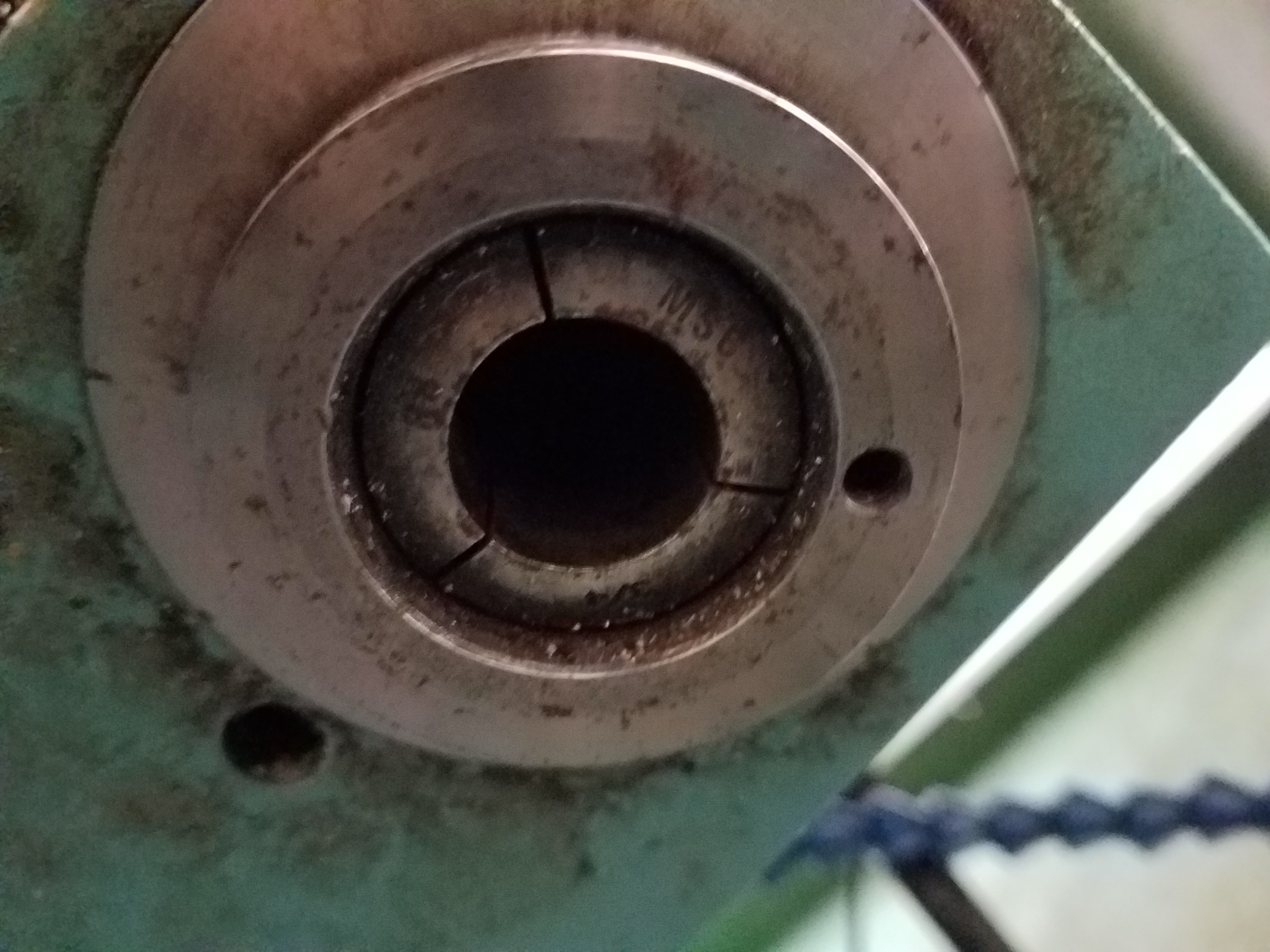
Question.... This is a picture of the tool clamp from underneath. There is a screw hole on the rim. Mine came as seen and the question is, "am I missing something here?" Also, I have been trying to read the proximity sensor and I am pretty sure it is working, but it is not sensing anything. I assume it is an index for the tool changer. Is there supposed to be a magnet or a piece of raised metal that it is supposed to detect?
Thanks
Steve
Thanks
Steve
Please Log in or Create an account to join the conversation.
Time to create page: 0.279 seconds