Light Machine Corp. Benchman XTr (retrofit)
- x-Intelitek Engineer
- Offline
- Premium Member
-

Less
More
- Posts: 113
- Thank you received: 22
01 Jun 2018 18:43 #111405
by x-Intelitek Engineer
Replied by x-Intelitek Engineer on topic Light Machine Corp. Benchman XTr (retrofit)
1 more thing,
Here is the top level diagram of your machine.
NOTE: This diagram is ONLY appropriate for a machine with high speed spindle, and 2 "stacked" control boards in the backpack on the machine.
Here is the top level diagram of your machine.
NOTE: This diagram is ONLY appropriate for a machine with high speed spindle, and 2 "stacked" control boards in the backpack on the machine.
The following user(s) said Thank You: genixia
Please Log in or Create an account to join the conversation.
- project-pegasus
-

- Visitor
-

01 Jun 2018 19:48 #111408
by project-pegasus
Replied by project-pegasus on topic Light Machine Corp. Benchman XTr (retrofit)
Wow! Thanks for posting those schematics, Engineer-X. I'm going to dig into this and see what I can figure out. Thanks again!
Please Log in or Create an account to join the conversation.
- project-pegasus
-
- Visitor
-
02 Jun 2018 03:11 #111435
by project-pegasus
Replied by project-pegasus on topic Light Machine Corp. Benchman XTr (retrofit)
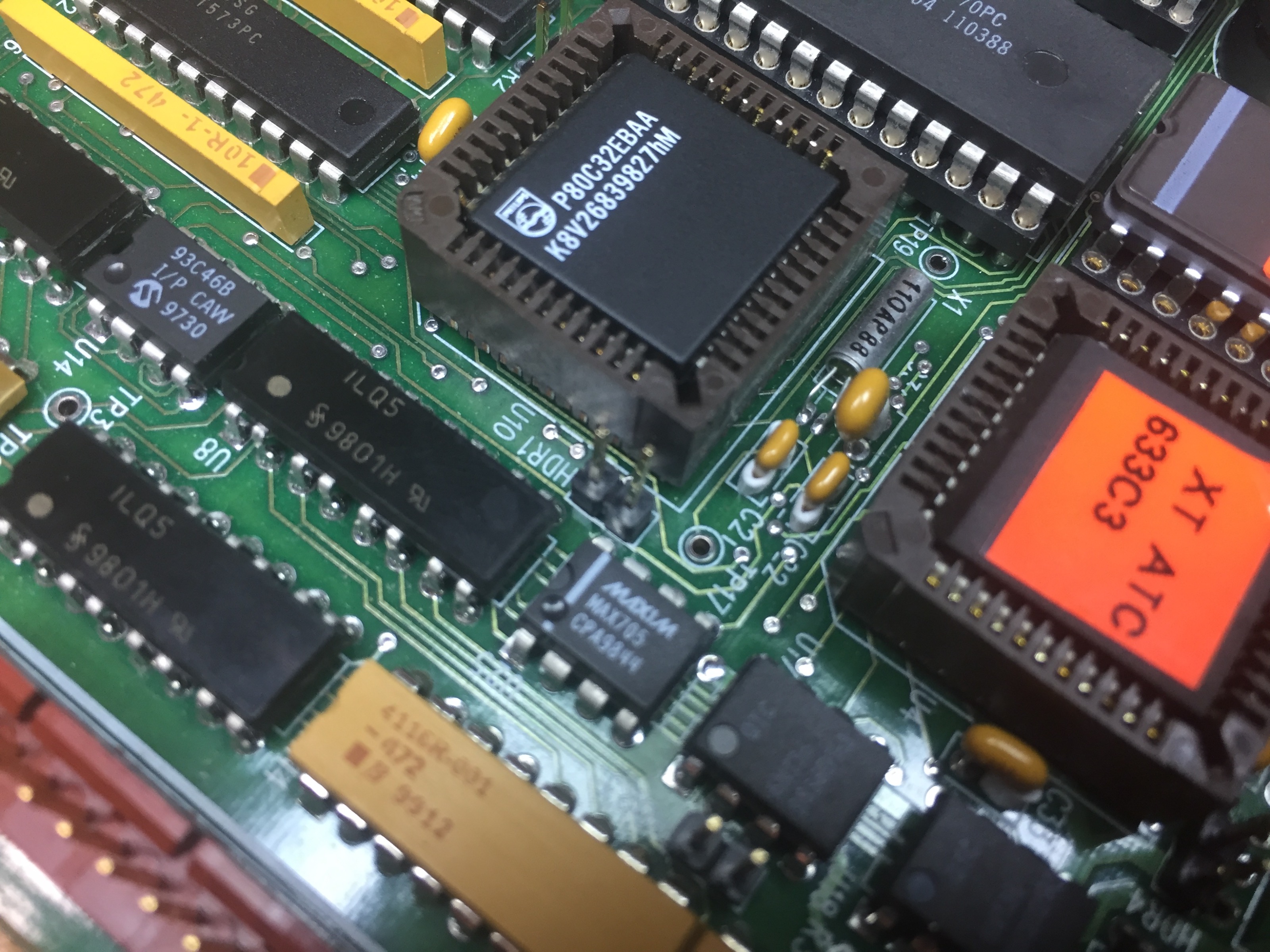
Two of the ILQ5 opto-couplers are bad; there's continuity both ways on one or two of their LEDs.
Anyone know of a good source for these, or a good replacement. Mouser and Digikey list them as obsolete.
Anyone know of a good source for these, or a good replacement. Mouser and Digikey list them as obsolete.
Please Log in or Create an account to join the conversation.
- genixia
- Offline
- Junior Member
-

Less
More
- Posts: 22
- Thank you received: 0
02 Jun 2018 05:10 #111445
by genixia
Replied by genixia on topic Light Machine Corp. Benchman XTr (retrofit)
Canada, $1.06. - www.futureelectronics.com/en/technologie...18001-ILQ5.aspx?IM=0
Some on ebay Australia too.
Some on ebay Australia too.
Please Log in or Create an account to join the conversation.
- project-pegasus
-
- Visitor
-
02 Jun 2018 07:11 #111448
by project-pegasus
Replied by project-pegasus on topic Light Machine Corp. Benchman XTr (retrofit)
Thanks for finding that, genixia. I did a little searching and found that the ILQ1 will also work, and they are still in production so I will probably go ahead and replace all the ILQ5s on the board. I'm finding that desoldering through-hole ICs is not fun.
Please Log in or Create an account to join the conversation.
- Muzzer
- Offline
- Elite Member
-

Less
More
- Posts: 266
- Thank you received: 42
02 Jun 2018 12:05 #111454
by Muzzer
Replied by Muzzer on topic Light Machine Corp. Benchman XTr (retrofit)
You may have done it by now but one way to remove dead ICs without risking ripping the tracks and vias from the board is to cut the pins individually (ideally right next to the body of the device), then you can heat and pull out the pins one at a time. Last thing you want right now is to damage the board obviously. You need some fine nosed cutters for this but it's worth either getting some or grinding down the nose of a larger tool to fit between the adjacent pins.
Seems an unusual / unlikely failure mode for an LED. If you measured with the board unpowered, you may simply have been seeing the reverse path back up through the other components. The usual problem with old optos is the gradual degradation of the current transfer ratio (CTR) so that they eventually stop activating the optotransistor on the other side of the barrier sufficiently for the connected circuit to operate correctly. However, that also requires replacement so you are probably doing the right thing either way.
Murray
Please Log in or Create an account to join the conversation.
- project-pegasus
-
- Visitor
-
02 Jun 2018 18:29 #111465
by project-pegasus
Replied by project-pegasus on topic Light Machine Corp. Benchman XTr (retrofit)
Thanks for the advice, Muzzer. Is there a way to definitively test optos on the board, unpowered?
Please Log in or Create an account to join the conversation.
- Muzzer
- Offline
- Elite Member
-
Less
More
- Posts: 266
- Thank you received: 42
02 Jun 2018 20:35 #111470
by Muzzer
Replied by Muzzer on topic Light Machine Corp. Benchman XTr (retrofit)
Not really. But if you can power the board up safely and operate the optos you may be able to see if the output circuits seem to behave - easier said than done perhaps, unless you have the right equipment (eg an oscilloscope). I assume that you have homed in on this part of the circuit because of apparent loss of signals thereabouts. I've no idea what the circuit looks like, so couldn't comment.
Please Log in or Create an account to join the conversation.
- x-Intelitek Engineer
- Offline
- Premium Member
-
Less
More
- Posts: 113
- Thank you received: 22
04 Jun 2018 11:38 #111591
by x-Intelitek Engineer
Replied by x-Intelitek Engineer on topic Light Machine Corp. Benchman XTr (retrofit)
I would recommend installing a machined contact IC socket in any position where you remove one of the DIP ICs. That way you can always remove it from the circuit in the future for more testing if it turns out that it is not the failed component. As long as J3, J4, J5, & J6 were not plugged in when you did the continuity test, you should be ok, there is nothing else in the LED circuits if they are unplugged.
I always tested them by removing the connectors and shorting the input pins to ground and looking for the outputs to change. For instance, short J3-2 to J3-3 and you should see a transition on U7-15 from +5V to GND when the short is present, and a return to +5V when the short is removed. Be careful not to short J3-3 to J3-4 as that is a direct power short.
Hopefully the replacement of these will go a long way towards making you toolchanger work again.
Please Log in or Create an account to join the conversation.
- project-pegasus
-
- Visitor
-
15 Jun 2018 03:06 #112389
by project-pegasus
Replied by project-pegasus on topic Light Machine Corp. Benchman XTr (retrofit)
It looks like I've managed to make things worse. A lot worse. Last week when I was checking some voltages on J8 of the ATC board I slipped and shorted a couple of the power pins and ZAP! Smoked the TD62003 at U26 and since that's the gate driver controlling the air cylinders, those no longer do anything at all. Whereas before this little mishap the air cylinders would actually work at first (at least until the ATC lost track of what position they were actually in) now there was no signal getting to the cylinders. It also actually damaged the COM1 port on the PC that I was connected to. So COM1 on the PC is now dead ( I did a loopback test using hyperterminal and, yeah, it's gone.) So I went ahead and replaced all the ILQ5s, installing the DIP sockets as Don suggested, and while I was at it I replaced the TD62003 on U26 that got fried. But the situation is still the same: no movement with the air cylinders. I checked voltages on the inputs of U26 and get nothing when I try to operate the ATC in the software. So obviously no signal is reaching U26 from the eeprom at U4. If that power short knocked out my COM port (though I'm not sure that's really the case, as it was a little buggy before this happened) it could have fried just about everything else on the board in the process. I'm tempted to replace the EEPROM but I'm not sure what that would entail. Would the replacement have to be flashed somehow, and how would I go about doing that? And what about the microprocessor on U10? Would it be possible to replace that if need be?
Please Log in or Create an account to join the conversation.
Time to create page: 0.222 seconds