Light Machine Corp. Benchman XTr (retrofit)
- project-pegasus
-

- Visitor
-

23 Jul 2019 22:23 #140362
by project-pegasus
Replied by project-pegasus on topic Light Machine Corp. Benchman XTr (retrofit)
I found this schematic, but I still need to figure out where each Hall lead connects in breakout pictured above. Anyone have a VMC 4000 with tool changer?

Please Log in or Create an account to join the conversation.
- x-Intelitek Engineer
- Offline
- Premium Member
-

Less
More
- Posts: 113
- Thank you received: 22
24 Jul 2019 12:18 #140424
by x-Intelitek Engineer
Replied by x-Intelitek Engineer on topic Light Machine Corp. Benchman XTr (retrofit)
It has been a long time since I worked on a 4000. If you can give me the PCB numbers in the system, I may be able to help.
Please Log in or Create an account to join the conversation.
- project-pegasus
-
- Visitor
-
25 Jul 2019 22:15 #140575
by project-pegasus
Replied by project-pegasus on topic Light Machine Corp. Benchman XTr (retrofit)
Thanks X! I'm trying to reconnect the Hall leads and power connections for the spindle. It looks like the Hall leads went to some sort of junction board on the right hand side of the rear panel:
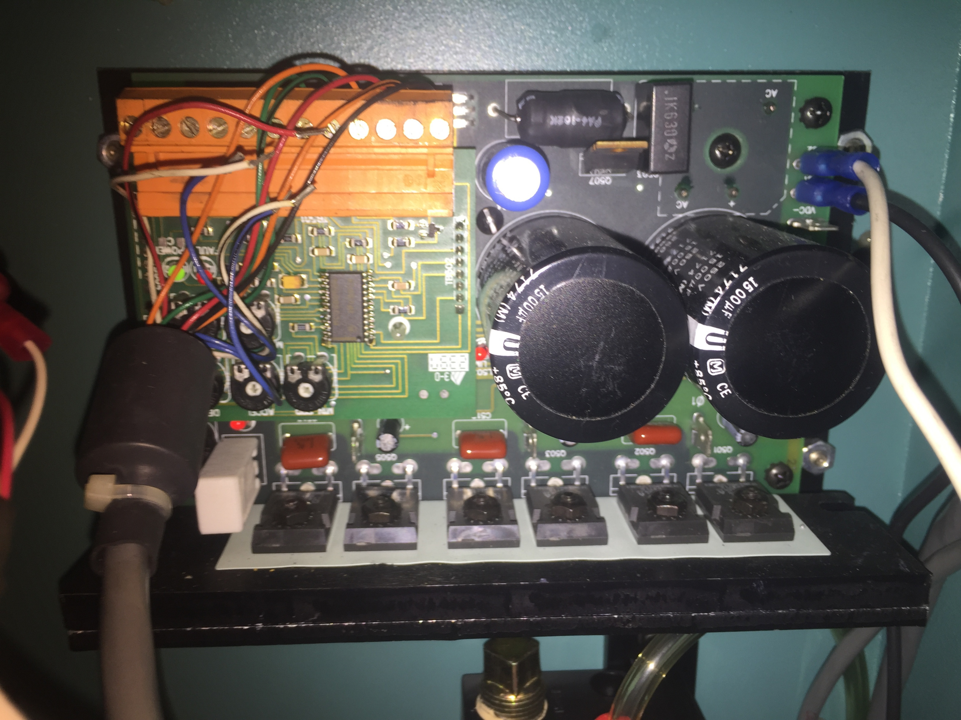
I've also attached pictures of main board to give you an idea of what PCB I'm working with
I've also attached pictures of main board to give you an idea of what PCB I'm working with
Please Log in or Create an account to join the conversation.
- andypugh
-

- Offline
- Moderator
-

Less
More
- Posts: 19879
- Thank you received: 4643
28 Jul 2019 18:11 #140828
by andypugh
Replied by andypugh on topic Light Machine Corp. Benchman XTr (retrofit)
If the hall sensors are in the wrong order then the motor will simply not run, or will run backwards.
You can just run through all 6 possible combinations to see which one works. The drawing shows which colour is which, and I would be surprised if they were not just ABC or CBA on the connector.
You can just run through all 6 possible combinations to see which one works. The drawing shows which colour is which, and I would be surprised if they were not just ABC or CBA on the connector.
Please Log in or Create an account to join the conversation.
- project-pegasus
-
- Visitor
-
29 Jul 2019 02:13 #140859
by project-pegasus
Replied by project-pegasus on topic Light Machine Corp. Benchman XTr (retrofit)
Thanks for that advice, Andy. Here's the trouble I'm running into. It looks like there were several slots on the spindle drive board that had multiple wires inserted. Like a wire from the spindle's Hall leads paired with a wire from the main control board. You can see the loose wires from the main board in picture of the spindle driver board posted above. Those aren't the Hall leads. And then there's the two wires from the spindle that each terminate in a two-pin header connector (also pictured above). Not sure what those are. I really need someone with one of these machines to help me out. Thanks.
Please Log in or Create an account to join the conversation.
- x-Intelitek Engineer
- Offline
- Premium Member
-
Less
More
- Posts: 113
- Thank you received: 22
29 Jul 2019 13:15 #140884
by x-Intelitek Engineer
Replied by x-Intelitek Engineer on topic Light Machine Corp. Benchman XTr (retrofit)
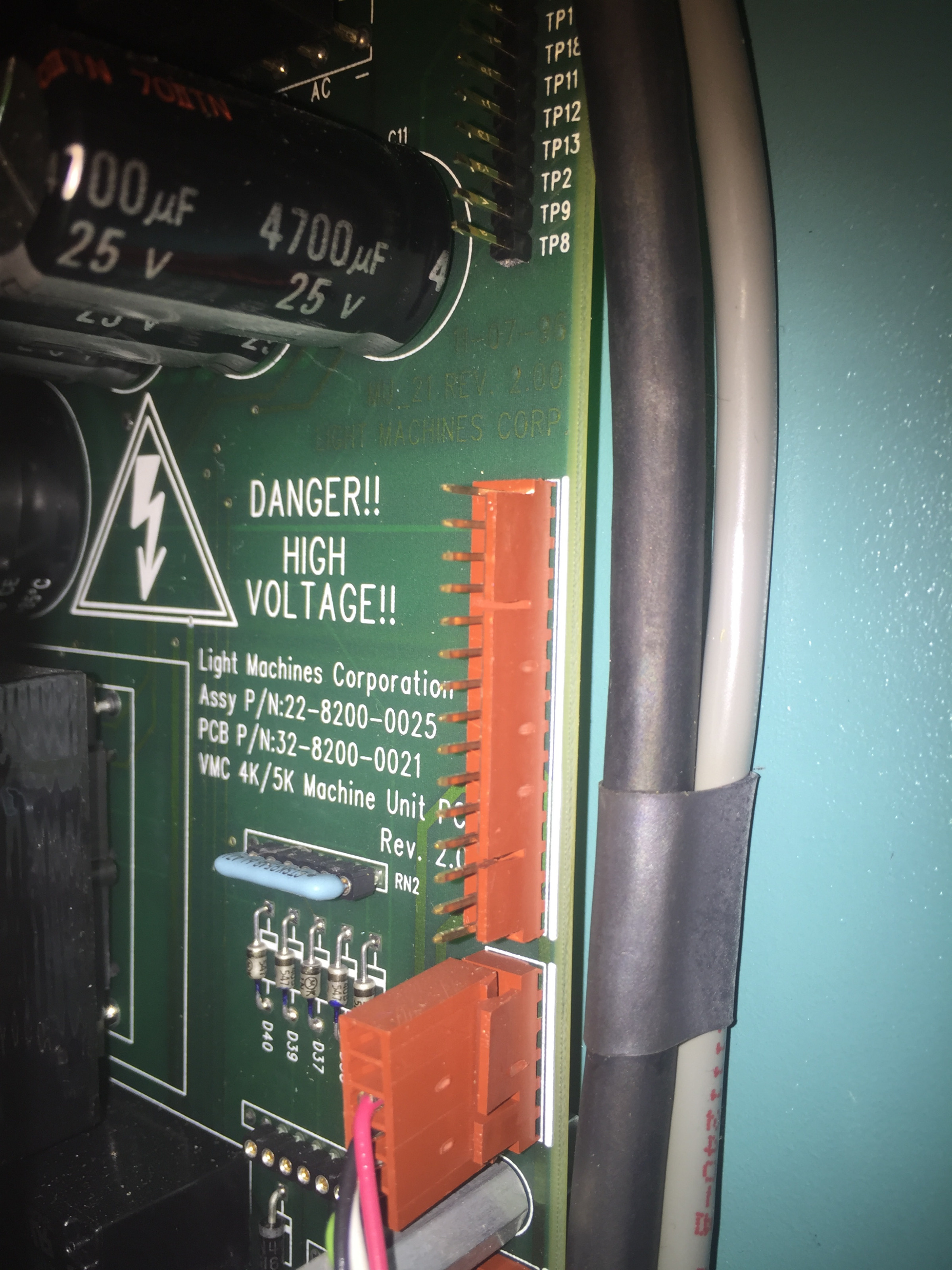
Do you have the part number of the cable on the left side of the first photo? There should be a label with the part number attached. I have some connection diagrams and can check based on the P/N.
Please Log in or Create an account to join the conversation.
- x-Intelitek Engineer
- Offline
- Premium Member
-
Less
More
- Posts: 113
- Thank you received: 22
29 Jul 2019 20:07 #140916
by x-Intelitek Engineer
Replied by x-Intelitek Engineer on topic Light Machine Corp. Benchman XTr (retrofit)
I have attached a photo of another (differrent) installation of that speed control.
(This is not wired exactly like your machine, so DO NOT COPY)
You can see that there are several locations with 2 wires in them.
I have also attached an explanation of the connections.
This should explain the connections from the motor to the speed control as well as the connections (Halls) that go to both the speed control and the control PCBs.
Once you give me the cable #, I should be able to give you more information.
Please Log in or Create an account to join the conversation.
- project-pegasus
-
- Visitor
-
29 Jul 2019 22:14 #140926
by project-pegasus
Replied by project-pegasus on topic Light Machine Corp. Benchman XTr (retrofit)
Thanks for posting that picture! Unfortunately I couldn't find any label on the cable we're talking about, just the manufacturer's number;

Please Log in or Create an account to join the conversation.
- x-Intelitek Engineer
- Offline
- Premium Member
-
Less
More
- Posts: 113
- Thank you received: 22
30 Jul 2019 14:07 #140951
by x-Intelitek Engineer
Replied by x-Intelitek Engineer on topic Light Machine Corp. Benchman XTr (retrofit)
Pegasus,
The attached file shows how to connect the motor to the speed control.
Pin 1 is the inboard-most location. It is the WHT wire in my previous photo.
The motor connects to pins 8-10 of the big orange connector and to the 3 male spade connections on the speed control.
The hall cells connect to the connector you show on pins: 24, 25, & 26. They are used strictly for determining spindle speed; whether it is turning or not and if it is at speed.
I am also attaching a copy of the schematic for your main control board (with the cuts and jumpers identified).
I drew this back in 1999 to develop a universal control board for next generation machine (Benchman XT).
I believe it is accurate, but please use it as a guide and not as 100% guaranteed fact.
Please let me know what else is needed.
Please Log in or Create an account to join the conversation.
- project-pegasus
-
- Visitor
-
31 Jul 2019 20:21 #141036
by project-pegasus
Replied by project-pegasus on topic Light Machine Corp. Benchman XTr (retrofit)
Thank you, X. That it going to help a lot. It might be a week or so before I can get back into the machine but I will let you know how it turns out. Thanks again.
Please Log in or Create an account to join the conversation.
Time to create page: 0.237 seconds