Emco PC turn 55 upgrade..
- turbo
-

- Offline
- Senior Member
-

Less
More
- Posts: 75
- Thank you received: 0
16 Nov 2016 02:13 #82855
by turbo
Replied by turbo on topic Emco PC turn 55 upgrade..
I finally got the little intel mobo today and loaded the wheezy 2.7. I let it update to 2.7.8 right away. I was able to open linuxcnc from the root terminal. When I try to launch it from the menu it gives me an error saying it needs rtapi.
I dug out my boxes of unloved projects and was thinking I should get my reprap working on the Beaglebone Black first before I mess with the lathe, plus I'm still waiting on capacitors. It seems like that is actually going to be a more complicated project since I want to use the ramps board I've already got with the BBB. So far I haven't even figured out how to change the image into an eMMC flasher image.
I dug out my boxes of unloved projects and was thinking I should get my reprap working on the Beaglebone Black first before I mess with the lathe, plus I'm still waiting on capacitors. It seems like that is actually going to be a more complicated project since I want to use the ramps board I've already got with the BBB. So far I haven't even figured out how to change the image into an eMMC flasher image.
Please Log in or Create an account to join the conversation.
- turbo
-
- Offline
- Senior Member
-
Less
More
- Posts: 75
- Thank you received: 0
17 Nov 2016 02:00 #82880
by turbo
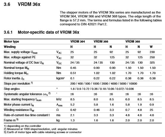
I'm trying to figure out the motor steps/rev. From this is it safe to assume that these are all 200 step/rev motors? I measured my ball screws at 2.5mm/rev, and confirmed that I've got .001mm resolution. So I would think that the Emco controls are running at 5000 steps/rev, since 2500 isn't an option. Is there a maximum relolution in Linuxcnc?
I replaced the capacitor on the original driver board today. I ran an m6x1 program I had ran before for testing. It seems that things have improved slightly but I still got the z axis error which stops the program.
Replied by turbo on topic Emco PC turn 55 upgrade..
The motor used for the axis is a VRDM366/50LHA ( PDF ), and the stepper drivers take differential input. (see page 15 of the PDF).
I'm trying to figure out the motor steps/rev. From this is it safe to assume that these are all 200 step/rev motors? I measured my ball screws at 2.5mm/rev, and confirmed that I've got .001mm resolution. So I would think that the Emco controls are running at 5000 steps/rev, since 2500 isn't an option. Is there a maximum relolution in Linuxcnc?
I replaced the capacitor on the original driver board today. I ran an m6x1 program I had ran before for testing. It seems that things have improved slightly but I still got the z axis error which stops the program.
Please Log in or Create an account to join the conversation.
- andypugh
-

- Offline
- Moderator
-

Less
More
- Posts: 19863
- Thank you received: 4636
17 Nov 2016 10:29 #82884
by andypugh
Replied by andypugh on topic Emco PC turn 55 upgrade..
Yes, it looks like 200 steps/rev motor and the other numbers refer to whatever microstepping is in use by the drives.I'm trying to figure out the motor steps/rev. From this is it safe to assume that these are all 200 step/rev motors?
Not for any practical purposes, no. However depending on the pulse-generator (software or hardware) you might run out of pulse-rate at very high microstep settings.Is there a maximum resolution in Linuxcnc?
Please Log in or Create an account to join the conversation.
- turbo
-
- Offline
- Senior Member
-
Less
More
- Posts: 75
- Thank you received: 0
21 Nov 2016 17:27 #83083
by turbo
Replied by turbo on topic Emco PC turn 55 upgrade..
Can anyone tell me how the controller communicates with the tool changer? I want to know if the original tool changer electronics are compatible with LinuxCNC and the 7i76.
Please Log in or Create an account to join the conversation.
- turbo
-
- Offline
- Senior Member
-
Less
More
- Posts: 75
- Thank you received: 0
05 Feb 2017 19:09 #87352
by turbo
Replied by turbo on topic Emco PC turn 55 upgrade..
Got a job and moved so I didn't touch the lathe for two months. The last thing I did before moving was put the toolerator 3000 together. I decided to just pull everything apart and label the wires and not try to get it running again to try to figure out what all the wires are with the scope and meter. Right now I'm trying to match the wires to the VFD with the 7I76.
The wires to the VFD are:
62 frequenz analog
7 GND 1
8 Sollwert (reference)
59 +24V
A1 Servo Ready
28 Reglerfreigabe (controller enable)
E4 R/L 0/1
39 GND 2
7I76 TB4 terminals
1 Spindle-
2 Spindle Out
3 Spindle+
4 NC
5 Spindle Ena-
6 Spindle Ena+
7 Spindle Dir-
8 Spindle Dir+
The only one I got hooked up is Spindle Out to Frequenz Analog.
Please Log in or Create an account to join the conversation.
- andypugh
-
- Offline
- Moderator
-
Less
More
- Posts: 19863
- Thank you received: 4636
07 Feb 2017 00:15 #87428
by andypugh
That's probably right. What voltage is Sollwert relative to GND?
At a guess I would be connecting Sollwert to Spindle+ and GND to Spindle-. Especially if there is 12 V or 10V between them on the multimeter.
I would guess that spindle-enable+ is 28, and spindle-enable- goes to GND2. I might be tempted to try that with a jumper wire first, though.
Replied by andypugh on topic Emco PC turn 55 upgrade..
The wires to the VFD are:
62 frequenz analog
7 GND 1
8 Sollwert (reference)
59 +24V
A1 Servo Ready
28 Reglerfreigabe (controller enable)
E4 R/L 0/1
39 GND 2
7I76 TB4 terminals
1 Spindle-
2 Spindle Out
3 Spindle+
4 NC
5 Spindle Ena-
6 Spindle Ena+
7 Spindle Dir-
8 Spindle Dir+
The only one I got hooked up is Spindle Out to Frequenz Analog.
That's probably right. What voltage is Sollwert relative to GND?
At a guess I would be connecting Sollwert to Spindle+ and GND to Spindle-. Especially if there is 12 V or 10V between them on the multimeter.
I would guess that spindle-enable+ is 28, and spindle-enable- goes to GND2. I might be tempted to try that with a jumper wire first, though.
Please Log in or Create an account to join the conversation.
- turbo
-
- Offline
- Senior Member
-
Less
More
- Posts: 75
- Thank you received: 0
07 Feb 2017 00:41 #87430
by turbo
Replied by turbo on topic Emco PC turn 55 upgrade..
I think I found the proper manual for the VFD now so I may be able to figure something out.
download.lenze.com/TD/E82EV__8200%20vect...5-90kW__v3-0__EN.pdf page 194 ish
download.lenze.com/TD/E82EV__8200%20vect...5-90kW__v3-0__EN.pdf page 194 ish
Please Log in or Create an account to join the conversation.
- turbo
-
- Offline
- Senior Member
-
Less
More
- Posts: 75
- Thank you received: 0
12 Feb 2017 01:30 #87851
by turbo
Replied by turbo on topic Emco PC turn 55 upgrade..
Apparently frequenz analog is a speed signal back to the controller and sollwert is the speed control signal. I should have enough of the wiring hooked up that I can move the x, z and spindle, but the pncconfig is hiding all the important connections from me.
Please Log in or Create an account to join the conversation.
- turbo
-
- Offline
- Senior Member
-
Less
More
- Posts: 75
- Thank you received: 0
13 Feb 2017 01:01 #87894
by turbo
Replied by turbo on topic Emco PC turn 55 upgrade..
Not Working
Spindle- to 7 GND
Spindle Out to 8 Analog Input
Spindle+ to +5VP on 7I76
NC
Spindle Ena- NC
Spindle Ena+ to 28 Controller inhibit 1=enable
Spindle Dir- to E4 CW0/CCW1
Spindle Dir+ NC
So the spindle won't do anything when I try to jog it in the pncconfig. It is also outputting 3.5V at Spindle out and isn't changing when I hit the jog. Spindle Enable plus has 0V and doesn't change when I try to jog it. The pin on the VFD that is supposed to be 5.2V is 8.5 for some reason.
Please Log in or Create an account to join the conversation.
- PCW
-

- Offline
- Moderator
-
Less
More
- Posts: 17927
- Thank you received: 5251
13 Feb 2017 16:03 #87913
by PCW
Replied by PCW on topic Emco PC turn 55 upgrade..
Those connections would not be expected to work
First, the ena and dir pins must always be used in +- pairs since they are isolated optorcoupler switch outputs
(that is that are not voltage outputs, they are the equivalent of relay contacts and can either be open
(no connection) or closed (connection between + and = pins)
The analog section expects to be powered by the 10V reference for the speed control potentiometer
if the drive does not supply this 10V, it must be externally supplied (12V is usually OK with scaling changes)
Do you have the spindle control manual or schematice or other documentation that shows the control pins?
The following user(s) said Thank You: turbo
Please Log in or Create an account to join the conversation.
Time to create page: 0.431 seconds