New Eagle Conversion
- lakeweb
-
 Topic Author
- Offline
- Senior Member
-

- Posts: 56
- Thank you received: 23
I'm watchdog timing out and still not sure how to set that up. But now I'd like to move the machine and see the servo voltages before I take this back to the shop and really move the machine.
I've got a volt meter on pin 2 and 3 of TB5. ( ENA0+, GND ), but it looks like all I'm getting is a floating pin. I have run the code and expect to see voltage to drive the servo. Yes, I know I will get a joint following error if I don't get the encoder to fake it out, but I'd like to know if I'm on the right track.
Please Log in or Create an account to join the conversation.
- tommylight
-

- Offline
- Moderator
-

- Posts: 21098
- Thank you received: 7205
Please Log in or Create an account to join the conversation.
- lakeweb
-
 Topic Author
- Offline
- Senior Member
-

- Posts: 56
- Thank you received: 23
I misunderstood, I thought those were a differential output. Now with ground and AOUT2 I see the voltage jump when I run. I think I'm ready to take this thing back out to the shop and see what kind of damage I can do. I have an E-STOP and will make sure that is real handy and working before I try to move the mill.
So in the morning I'll get a fire going in the stove and spend the day at it. There will be a lot of details like limit switches, power the servo amp, coolant, Just had to list them. I'm going to document this thing in detail as my son will inherit it. Hopefully I'll be posting happy pictures tomorrow afternoon!
Best, Dan.
Please Log in or Create an account to join the conversation.
- tommylight
-

- Offline
- Moderator
-

- Posts: 21098
- Thank you received: 7205
All this is to prevent servo drives taking off and damaging something. With enable and encoders wired properly even if the motors take off, linuxcnc will disable the drives preventing damage.
Regards
Tom
Please Log in or Create an account to join the conversation.
- lakeweb
-
 Topic Author
- Offline
- Senior Member
-

- Posts: 56
- Thank you received: 23
Thanks. The servo amp set had just one 24 volts to sink that would power it up, at least, the best that I could find while tracing wires while the amp was on the bench. So I used an e stop to break that sink.
At first my hand was so ready to slap that thing. I got side tracked for a lot of the day but the servos are up and running! I'll have to use a dial indicator to be sure the glass is 5um, but a measuring tape say it is so. I still have a lot to learn and do. I can't move faster than 5 ipm without a joint error. And I'll have to trim the zero because there is about a 2 second pulse as the servo bounces off the encoder. It does run smooth while moving. I need to spend an uninterrupted day out there to dress wires and get the limits and M stuff hooked up.
Best, Dan.
Please Log in or Create an account to join the conversation.
- lakeweb
-
 Topic Author
- Offline
- Senior Member
-

- Posts: 56
- Thank you received: 23
net estop-out <= hm2_[HOSTMOT2](BOARD).0.7i77.0.0.input-00
net both-home-y <= hm2_[HOSTMOT2](BOARD).0.7i77.0.0.input-01
net both-home-z <= hm2_[HOSTMOT2](BOARD).0.7i77.0.0.input-02
So I'm assuming that both-home-y and estop-out are preset keywords?
Also...
There seems to be an offset voltage from the 7i77 to the servos when stopped. Like .1 volts so the servos keep drifting and bouncing off the encoder change.
And!!
I'm completely clueless why I've got SCALE = 2540 rather than 25400 or 50800 with 5um steps.
Thanks, Dan.
Please Log in or Create an account to join the conversation.
- PCW
-

- Away
- Moderator
-

- Posts: 17514
- Thank you received: 5118
So I'm assuming that both-home-y and estop-out are preset keywords?
No those are signal names. They can have almost any name, the only things that are
hardwired are pin and parameter names
so
net both-home-x <= hm2_[HOSTMOT2](BOARD).0.7i77.0.0.input-01
net both-home-x <= axis.0.home-sw-in
is exactly the same as
net weird-signal-name23 <= hm2_[HOSTMOT2](BOARD).0.7i77.0.0.input-01
net weird-signal-name23 <= axis.0.home-sw-in
both simple connect hardware pin hm2_[HOSTMOT2](BOARD).0.7i77.0.0.input-01 to motion pin axis.0.home-sw-in
Please Log in or Create an account to join the conversation.
- lakeweb
-
 Topic Author
- Offline
- Senior Member
-

- Posts: 56
- Thank you received: 23
Thanks. By searching on 'axis.0.pos-lim-sw-in' I found some stuff. And it seems that this thing is wired with double pole lines such that:
net lim_out_x <= hm2_[HOSTMOT2](BOARD).0.7i77.0.0.input-00-not
net lim_out_x => axis.0.pos-lim-sw-in axis.1.pos-lim-sw-in axis.2.pos-lim-sw-in
Does what I need. the other two lines are also hooked to the switches and without further digging I'll assume that is how you figure which switch actually got hit.
But where do the likes of 'axis.0.pos-lim-sw-in' get described for what they actually do? I've only found it in examples.
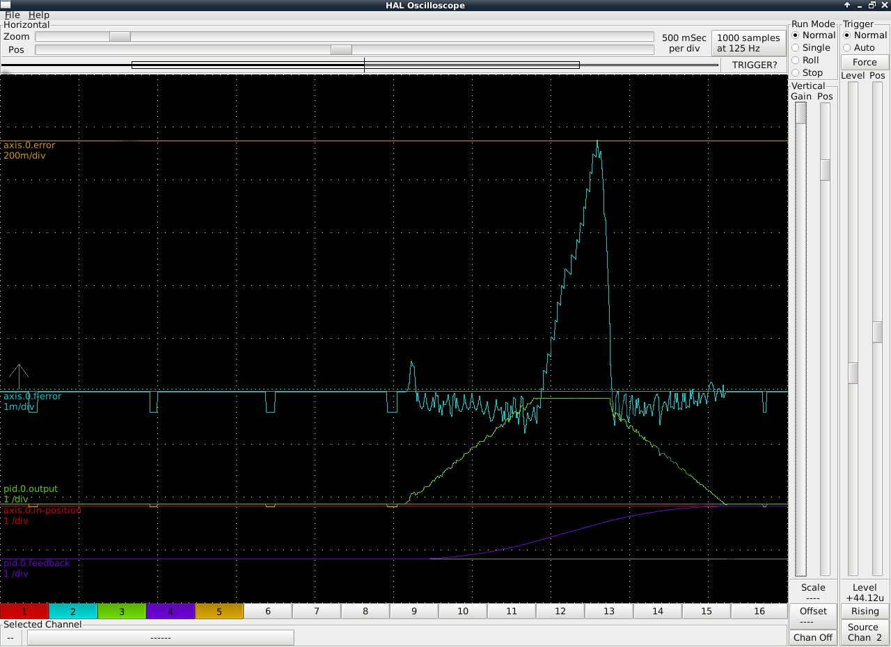
When I tuned up before I did not let the table get to full speed and settle. Now with the max rate turned down, I get:
The error just keeps building and I'll eventually trip a joint follow. I'm not sure how this gets fixed. And you can see the drift and corrections before the move. I am trying to be sure it is not some kind of ground loop on my side. BIAS has no effect and when linuxcnc is not powered, there is no drift.
Also, when at 1m per division does this translate to .001 inches?
Please Log in or Create an account to join the conversation.
- PCW
-

- Away
- Moderator
-

- Posts: 17514
- Thank you received: 5118
But where do the likes of 'axis.0.pos-lim-sw-in' get described for what they actually do? I've only found it in examples.
man motion
Can you post you tuning parameters?
As far as the drift/correction you may need to
zero the velocity command offset in your drives (probably a potentiometer)
Please Log in or Create an account to join the conversation.
- lakeweb
-
 Topic Author
- Offline
- Senior Member
-

- Posts: 56
- Thank you received: 23
[TRAJ]

AXES =                  3
# COORDINATES =         X Y Z R P W
COORDINATES =           X Y Z
HOME =                  0 0 0 0
LINEAR_UNITS =          inch
ANGULAR_UNITS =         degree
CYCLE_TIME =            0.010
DEFAULT_VELOCITY =      2.1
MAX_VELOCITY =          2.1
DEFAULT_ACCELERATION =  2.1
MAX_ACCELERATION =      2.1
NO_FORCE_HOMING =       1


#######################################
[AXIS_0]

TYPE =                  LINEAR
MAX_VELOCITY =          1.0
MAX_ACCELERATION =      2.0
BACKLASH =              0.000
FERROR =                1
MIN_FERROR =            .1

INPUT_SCALE =           2540

OUTPUT_SCALE =          1.000
OUTPUT_OFFSET =         -0.01
MAX_OUTPUT =            2

MIN_LIMIT =             -3.0
MAX_LIMIT =             10.0
HOME =                  0.000
HOME_OFFSET =           0.0
HOME_SEARCH_VEL =       0.0
HOME_LATCH_VEL =        0.0
HOME_USE_INDEX =        NO
HOME_IGNORE_LIMITS =    YES
HOME_SEQUENCE =         1

# PID tuning params
DEADBAND =              0.00015
P =                     220
I =                     0
D =                     0
FF0 =                   0
FF1 =                   2.5
#FF1 =                   1
FF2 =			0.02
#FF2 =			0
BIAS =                  0
Yes, I can zero the amp, did that earlier. But then when linuxcnc is not powered, it will drift as it gets a true zero volts on the output. If there is no way to correct the offset from the 7i77 I guess I will end up using the drive enables and running wires to the amp limits. I haven't tested but I'll guess the amps would still drift as it would create a true pseudo zero.
Thanks, Dan.
Please Log in or Create an account to join the conversation.


