New Machine Build: Bridgeport R2E4 Series II
- tightmopedman9
- Offline
- Senior Member
-

Less
More
- Posts: 73
- Thank you received: 7
21 Aug 2018 18:38 #116410
by tightmopedman9
Replied by tightmopedman9 on topic New Machine Build: Bridgeport R2E4 Series II
I made some progress in tuning the y axis. Tachometer gain from the factory is set for a maximum of 60v, my servos put out out 9.5 v/kRPM, and with a max RPM of 4000 the max voltage is 38v. The datasheet says to put a throughole resistor in series with the factory 50k resistor to increase gain. I didn't have any through hole resistors, and it seemed harder to extract solder out of the PCB holes so I just replaced the 50k resistor with a 33k resistor, effectively scaling the max voltage to 43V. This allowed me to get much finer control on the loop gain and get more reasonable results from tuning.
I set the PID maxerror to 0 in the .ini, and increased the max acceleration to 18. This turned out to be too high, which caused a spike in f error in initial movement and caused some nasty over and undershoot. I lowered the value to 15 and had much better results.
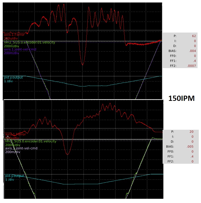
At first I had a problem with oscillation during long higher feed movements (70IPM+), I could get the oscillation to go away by a reduction in P, but this lead to a large static f-error. I was able to center the error with a little bit of bias, and reduced the P to minimize oscillation. A little FF1 to help with initial lag and FF2 to minimize overshoot at acceleration change points.
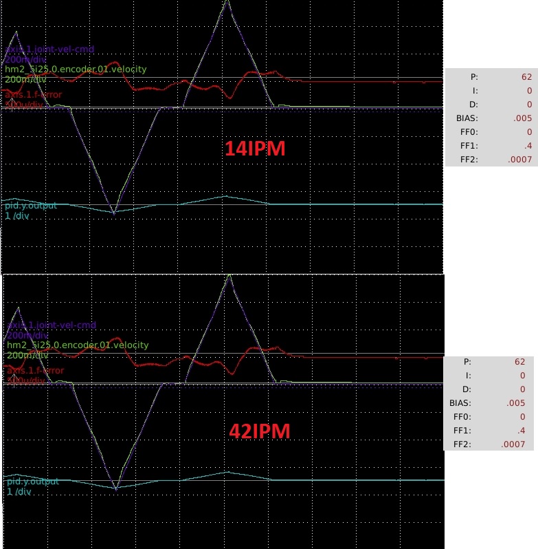
Based on the following comparison at my machine's max speed (limited by the input voltage of the 30a8) it looks like I should probably reduce my P value from the current 62. I need to make another comparison with the bias and FF2 set the same.
I set the PID maxerror to 0 in the .ini, and increased the max acceleration to 18. This turned out to be too high, which caused a spike in f error in initial movement and caused some nasty over and undershoot. I lowered the value to 15 and had much better results.
At first I had a problem with oscillation during long higher feed movements (70IPM+), I could get the oscillation to go away by a reduction in P, but this lead to a large static f-error. I was able to center the error with a little bit of bias, and reduced the P to minimize oscillation. A little FF1 to help with initial lag and FF2 to minimize overshoot at acceleration change points.
Based on the following comparison at my machine's max speed (limited by the input voltage of the 30a8) it looks like I should probably reduce my P value from the current 62. I need to make another comparison with the bias and FF2 set the same.
Please Log in or Create an account to join the conversation.
- andypugh
-

- Offline
- Moderator
-

Less
More
- Posts: 19876
- Thank you received: 4642
21 Aug 2018 22:49 #116433
by andypugh
Replied by andypugh on topic New Machine Build: Bridgeport R2E4 Series II
I-gain is normally the way to get rid of steady-state error.
Please Log in or Create an account to join the conversation.
- tightmopedman9
- Offline
- Senior Member
-
Less
More
- Posts: 73
- Thank you received: 7
25 Aug 2018 01:27 - 25 Aug 2018 01:29 #116569
by tightmopedman9
Replied by tightmopedman9 on topic New Machine Build: Bridgeport R2E4 Series II
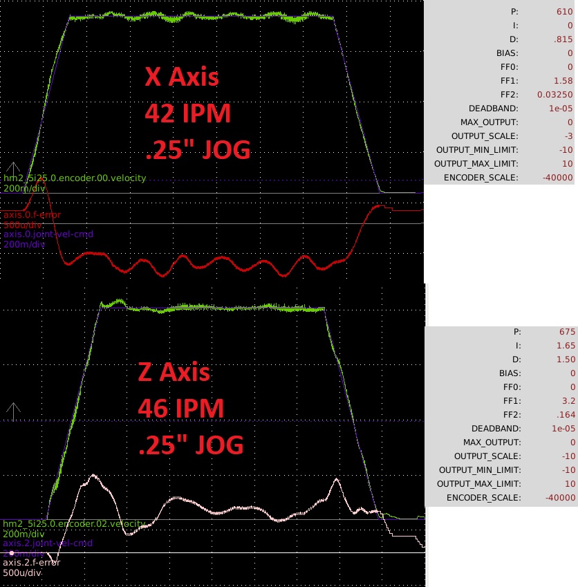
I spent more time trying to tune the servos in tachometer mode, but couldn't get them to run well at all. F-error was quite high and axis motion was quite jerky and sounded bad; no amount of tuning was able to get good results. I ended up switching to torque mode, and although it took more time tuning (not by much though) the servos are running much better. There is a spike of f-error at the beginning of movement, there is a short delay between actual velocity and commanded. Is there any way to tune around this?
I ended up using a cheap 24V power supply from Amazon and ditched the factory +24V, -22V supply. I also picked up a opto isolated relay board to trigger the spindle brake and varispeed pulley adjustments. I think both together cost me less than $30.
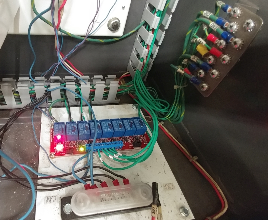
I still need to do a lot of wire clean up, and wire in a few more things. I want to connect the servo current output signal from each axis so that I can monitor servo load. I was thinking I would try and integrate a fault into the system to E-stop if a servo consumed too much current for a given time.
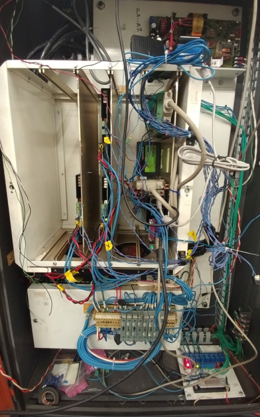
I was finally able to make my first chips! I put up the sides of the enclosure for testing, but I still need to do the front. I plan on running flood coolant, so I'd like to keep as much of it in the enclosure as I can.

This machine is in excellent condition, I think this is the quietest varispeed heard I've ever head. The spindle has less than .0001" of runout at 1". Also, the head is perfectly trammed and nodded, to within better than I can even measure. Not that I've done anything demanding yet, but I can already tell it's worlds better than my old clapped out Sharpe.
I have a WJ200 VFD running the spindle motor, and I have it connected via Modbus to EMC2. I can ping the VFD and get back relevant parameters through terminal, but I can't seem to turn it on via EMC2. In the .hal I initialize the VFD with:
loadusr -W wj200_vfd
setp wj200_vfd.0.mbslaveaddr 1
I can see the HAL pins in halconfiguration, and I can see the state of pins trigger when I issue the following commands:
setp wj200_vfd.0.enable TRUE
setp wj200_vfd.0.run TRUE
However, nothing happens, the VFD doesn't start. I've configured the options on the VFD for control via Modbus, so I'm not sure what else to try. Do I need to add more information into my .hal file?
I ended up using a cheap 24V power supply from Amazon and ditched the factory +24V, -22V supply. I also picked up a opto isolated relay board to trigger the spindle brake and varispeed pulley adjustments. I think both together cost me less than $30.
I still need to do a lot of wire clean up, and wire in a few more things. I want to connect the servo current output signal from each axis so that I can monitor servo load. I was thinking I would try and integrate a fault into the system to E-stop if a servo consumed too much current for a given time.
I was finally able to make my first chips! I put up the sides of the enclosure for testing, but I still need to do the front. I plan on running flood coolant, so I'd like to keep as much of it in the enclosure as I can.
This machine is in excellent condition, I think this is the quietest varispeed heard I've ever head. The spindle has less than .0001" of runout at 1". Also, the head is perfectly trammed and nodded, to within better than I can even measure. Not that I've done anything demanding yet, but I can already tell it's worlds better than my old clapped out Sharpe.
I have a WJ200 VFD running the spindle motor, and I have it connected via Modbus to EMC2. I can ping the VFD and get back relevant parameters through terminal, but I can't seem to turn it on via EMC2. In the .hal I initialize the VFD with:
loadusr -W wj200_vfd
setp wj200_vfd.0.mbslaveaddr 1
I can see the HAL pins in halconfiguration, and I can see the state of pins trigger when I issue the following commands:
setp wj200_vfd.0.enable TRUE
setp wj200_vfd.0.run TRUE
However, nothing happens, the VFD doesn't start. I've configured the options on the VFD for control via Modbus, so I'm not sure what else to try. Do I need to add more information into my .hal file?
Last edit: 25 Aug 2018 01:29 by tightmopedman9.
Please Log in or Create an account to join the conversation.
- andypugh
-
- Offline
- Moderator
-
Less
More
- Posts: 19876
- Thank you received: 4642
28 Aug 2018 15:14 #116712
by andypugh
Maybe a hint of FF1 (or FF2)
Replied by andypugh on topic New Machine Build: Bridgeport R2E4 Series II
there is a short delay between actual velocity and commanded. Is there any way to tune around this?
Maybe a hint of FF1 (or FF2)
Please Log in or Create an account to join the conversation.
- tightmopedman9
- Offline
- Senior Member
-
Less
More
- Posts: 73
- Thank you received: 7
01 Sep 2018 20:14 #116958
by tightmopedman9
Replied by tightmopedman9 on topic New Machine Build: Bridgeport R2E4 Series II
Do I have my coordinate system setup incorrectly? My generated G-code is directing the machine to go to the incorrect coordinates, and I think it is because I have my coordinate system setup incorrectly.
I set up the coordinates to what I thought was conventional. Positive X is towards the right, positive Y is the table moving inwards towards the machine (away from the operator) and positive Z is the quill moving up (away from the table). The home position is in the far back right, which means any move in the G53 coordinate system has to be a negative number.
I'm trying to mill a simple round pocket, and I have the touch off point set as the front left of stock. I probe the front left corner and set the G54 coordinate to 0 after doing so. When I run the program the cutter move to start milling as if the coordinates were reversed.
This is a picture of how I have the part touch off setup.
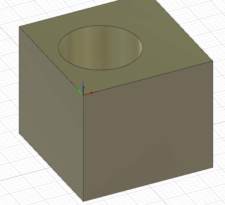
Please Log in or Create an account to join the conversation.
- pippin88
- Offline
- Elite Member
-

Less
More
- Posts: 263
- Thank you received: 51
01 Sep 2018 23:20 #116964
by pippin88
Replied by pippin88 on topic New Machine Build: Bridgeport R2E4 Series II
You need to think of the tool moving, not the table. Takes a little getting used to on a moving table machine.
The CAM software is all based on tool movements.
X+ means tool moving to the right (which means the table moves to the left).
Y+ means tool moving away from the operator (which means the table moves towards the operator).
Z+ means tool moves up
The CAM software is all based on tool movements.
X+ means tool moving to the right (which means the table moves to the left).
Y+ means tool moving away from the operator (which means the table moves towards the operator).
Z+ means tool moves up
The following user(s) said Thank You: andypugh
Please Log in or Create an account to join the conversation.
- tightmopedman9
- Offline
- Senior Member
-
Less
More
- Posts: 73
- Thank you received: 7
11 Sep 2018 23:40 #117371
by tightmopedman9
Replied by tightmopedman9 on topic New Machine Build: Bridgeport R2E4 Series II
Thanks for that, that makes much more sense. I was very confused when setting up the coordinates, as they intuitively didn't seem to make sense. With the new setup I can run CAM as expected.
I'd like to separate my spindle brake and spindle control. Right now the spindle brake is engaged whenever the spindle isn't spinning. My pneumatic brake is quite loud, so I'd rather not run the brake unless I need to do a tool change. Being a manual machine I'm happy to just hit a button to engage the brake when needed. Unfortunately, I can't find where the spindle motion is tied to the brake in any of my HAL files. Is this a function internal to AXIS?
I'd like to separate my spindle brake and spindle control. Right now the spindle brake is engaged whenever the spindle isn't spinning. My pneumatic brake is quite loud, so I'd rather not run the brake unless I need to do a tool change. Being a manual machine I'm happy to just hit a button to engage the brake when needed. Unfortunately, I can't find where the spindle motion is tied to the brake in any of my HAL files. Is this a function internal to AXIS?
Please Log in or Create an account to join the conversation.
- andypugh
-
- Offline
- Moderator
-
Less
More
- Posts: 19876
- Thank you received: 4642
11 Sep 2018 23:43 #117372
by andypugh
No, Axis does almost nothing with hardware.
Is it possible that the brake is operated by an output from the spindle drive / VFD. These often have at least one relay output, that can be configured for various purposes.
Replied by andypugh on topic New Machine Build: Bridgeport R2E4 Series II
Is this a function internal to AXIS?
No, Axis does almost nothing with hardware.
Is it possible that the brake is operated by an output from the spindle drive / VFD. These often have at least one relay output, that can be configured for various purposes.
Please Log in or Create an account to join the conversation.
- tightmopedman9
- Offline
- Senior Member
-
Less
More
- Posts: 73
- Thank you received: 7
11 Sep 2018 23:46 - 11 Sep 2018 23:47 #117374
by tightmopedman9
Replied by tightmopedman9 on topic New Machine Build: Bridgeport R2E4 Series II
Are you talking about a physical relay, integral to the VFD? If so, then no. I have the VFD connected via Modbus to EMC. The spindle brake is controlled by output-02 tied to an opto-isolated relay.
VFD is WJ200 btw.
VFD is WJ200 btw.
Last edit: 11 Sep 2018 23:47 by tightmopedman9.
Please Log in or Create an account to join the conversation.
- andypugh
-
- Offline
- Moderator
-
Less
More
- Posts: 19876
- Thank you received: 4642
12 Sep 2018 08:56 #117382
by andypugh
When you said that you couldn't see where it was connected in the HAL I assumed that you didn't know that it was controlled by a GPIO.
So, if it is output-02, what signal controls that pin, and what else is that signal connected to?
Replied by andypugh on topic New Machine Build: Bridgeport R2E4 Series II
The spindle brake is controlled by output-02 tied to an opto-isolated relay.
When you said that you couldn't see where it was connected in the HAL I assumed that you didn't know that it was controlled by a GPIO.
So, if it is output-02, what signal controls that pin, and what else is that signal connected to?
Please Log in or Create an account to join the conversation.
Time to create page: 0.527 seconds