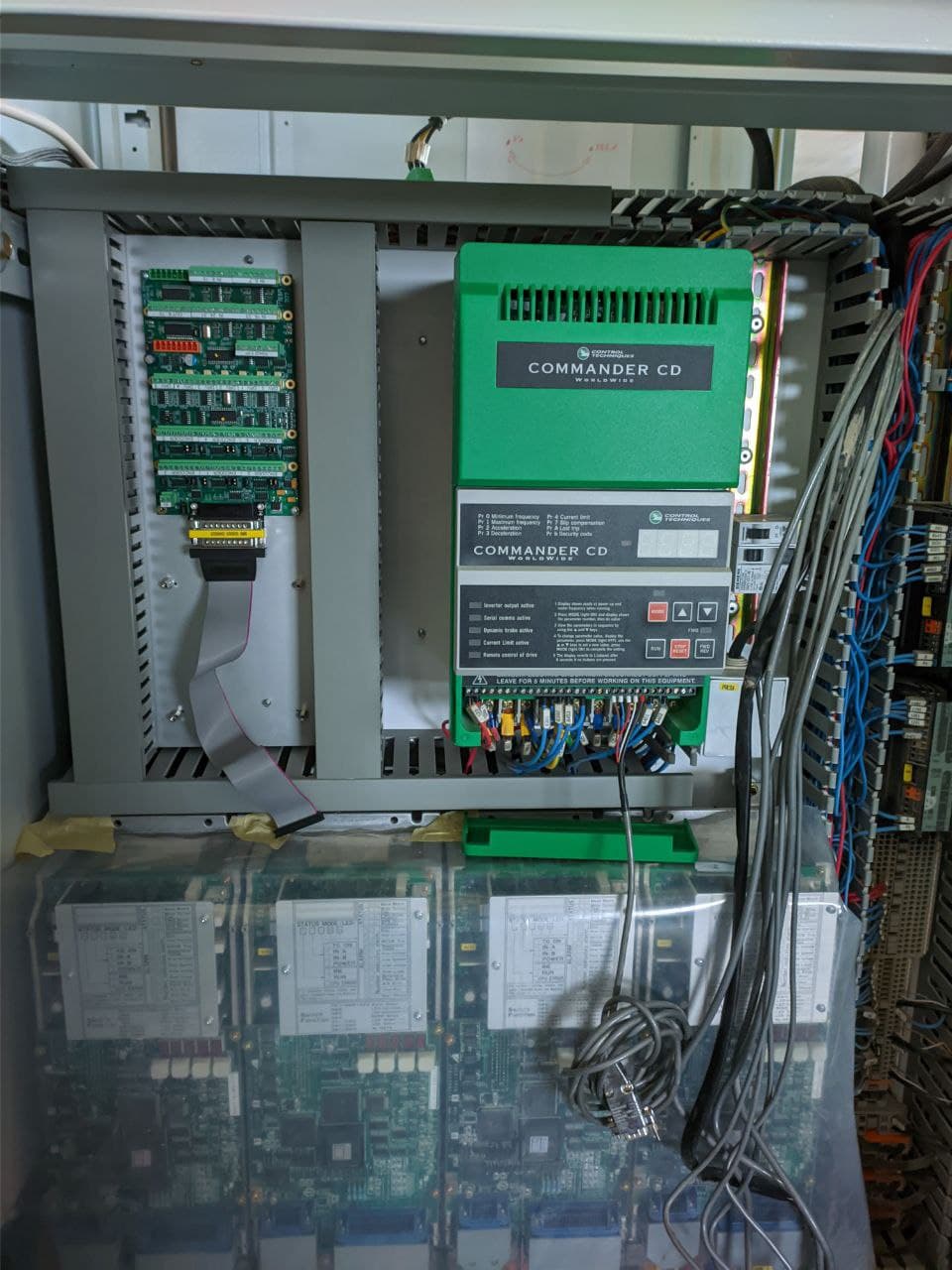
Another Biesse Rover 322
- ehb
- Offline
- Junior Member
-

Less
More
- Posts: 38
- Thank you received: 5
02 Feb 2022 20:00 #233828
by ehb
Replied by ehb on topic Another Biesse Rover 322
Thanks a lot for the link to your github repo! That's a lot of code, but I see comments and readable function and variable names. I like that so far! 
Regarding modules: As I said, CNi did not have any documentation about the communication protocol, but they sent me two-page brochures of SI816N, SIR88N, SI24N, SO24N and SO816. I've attached the PDF for SIR88N. My modules only say SIR88, without the N, so I'm not sure if they just omitted the N on the front lable or if they're two different things.
If my Biesse indeed has the SIR88N, then according to the PDF, the inputs should be sinking, which contradicts what the Biesse schematics and Yaskawa manual say.
About field voltages: Some of the Mesa cards have VIN and VFIELD separate. I was thinking about putting P1 on VIN and P2/P3 (depending on the module position) to VFIELD. Did you do the same?
Please Log in or Create an account to join the conversation.
- ehb
- Offline
- Junior Member
-

Less
More
- Posts: 38
- Thank you received: 5
02 Feb 2022 20:09 - 02 Feb 2022 20:10 #233831
by ehb
Replied by ehb on topic Another Biesse Rover 322
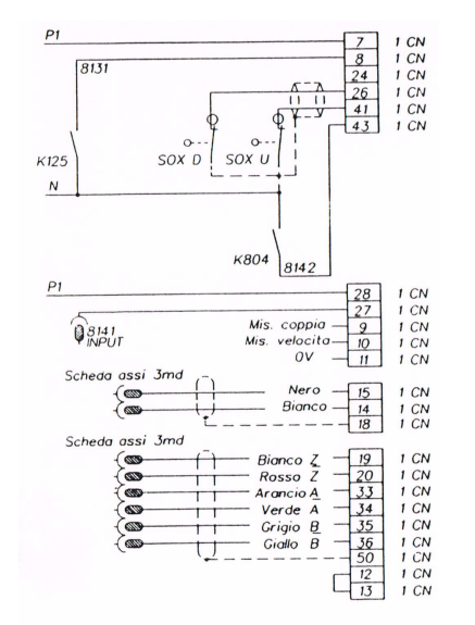
This is page 72 from the Biesse schematics. On the left side, we see input 8141 going to pin 27 on the Yaskawa drive connector (X) in this case).
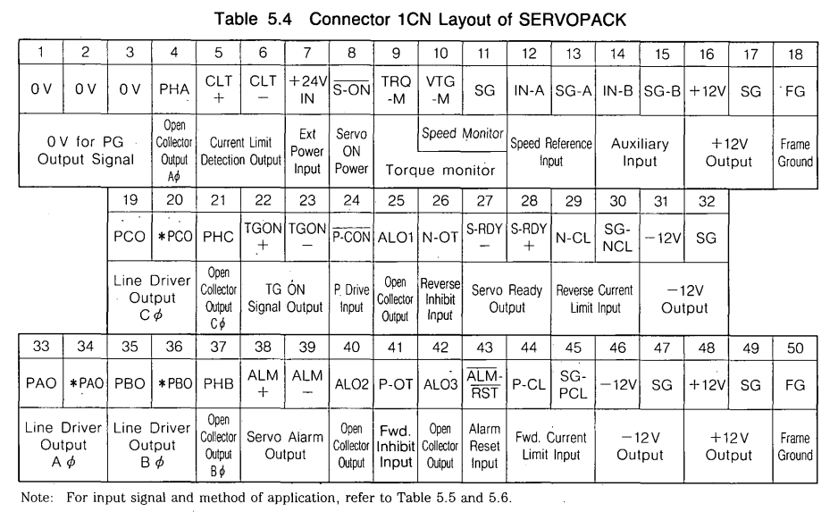
And this the connector pinout from the Yaskawa manual.
In fact, I now see P1 is connected to pin 28 - so I guess it's an isolated output which sources whatever is connected on pin 28 to pin 27. Which would indeed make the inputs sinking, which also means I was on the wrong track for a whole while and I can just hook this cable (pin 27, formerly going to input 8141) up to a 7i77 input.
I think I see clearly now, or am I wrong again?
Attachments:
Last edit: 02 Feb 2022 20:10 by ehb.
Please Log in or Create an account to join the conversation.
- bevins
-
- Offline
- Platinum Member
-

Less
More
- Posts: 1942
- Thank you received: 338
03 Feb 2022 12:42 #233869
by bevins
Replied by bevins on topic Another Biesse Rover 322
P1 is 24vdc.
You can see that in the beginning of the schematics and on the modules. That is what Biesse labels the first iteration of 24vdc.
The P1 is what ios powering the digital side of the drive.
Those modules are the RS485 modules that you cannot use. Those are inputs and outputs.
You need to provide a relay for each of those outputs and the inputs you can take directly into 7i77 if you are using the 24vdc from tyhe 3 phase rectifier in the machine. You need to watch which voltage you are using.
The following user(s) said Thank You: ehb
Please Log in or Create an account to join the conversation.
- bevins
-

- Offline
- Platinum Member
-

Less
More
- Posts: 1942
- Thank you received: 338
03 Feb 2022 12:45 #233870
by bevins
Replied by bevins on topic Another Biesse Rover 322
The N and P1 is the 24VDC for your drive logic. The inputs in the drive needs the 24vdc common to see an input.
P1 - +24vdc
N - com
P1 - +24vdc
N - com
The following user(s) said Thank You: ehb
Please Log in or Create an account to join the conversation.
- bevins
-

- Offline
- Platinum Member
-

Less
More
- Posts: 1942
- Thank you received: 338
03 Feb 2022 13:01 #233875
by bevins
Replied by bevins on topic Another Biesse Rover 322
Your ideas on VIN and field power are not ok. I just went back and read them. VIN is logic power and P1,P2,P3 is the same power but different iterations. You get get P2 and P3 after some logic or when it passes through a relay. Would have to look in your schematics but you really need to look at this setup carefully.
The following user(s) said Thank You: ehb
Please Log in or Create an account to join the conversation.
- ehb
- Offline
- Junior Member
-

Less
More
- Posts: 38
- Thank you received: 5
04 Feb 2022 19:18 #233991
by ehb
Replied by ehb on topic Another Biesse Rover 322
Thanks for pointing this out! You're right, I carelessly assumed P1 (of course 24V) would just "be there" (from the rectifier) when the machine is turned on and P2 and P3 when the machine was put on enable. This is not what happens!
I'm not 100% certain on all of it yet, need some more time to think it through and study the schematics and machine. So please don't pull your hair on my lack of understanding, it takes me some time, sometimes.
I'll have a friend (knowledgable electrician) come over if I can't figure it out, before I hook anything up.
However, by now I realized that the original power supply inside of the original RT480 control comes into play somehow. Since this will go, I need another source of 24V, which should power all of the Mesas VIN and possibly the 7i77's VFIELD too. VFIELD of the other cards could then be P2 and P3 I guess? So the question is where I take this 24V from - from the machines rectifier before all other logic, or from a separate, added, power supply. As I said, still trying to get it together.
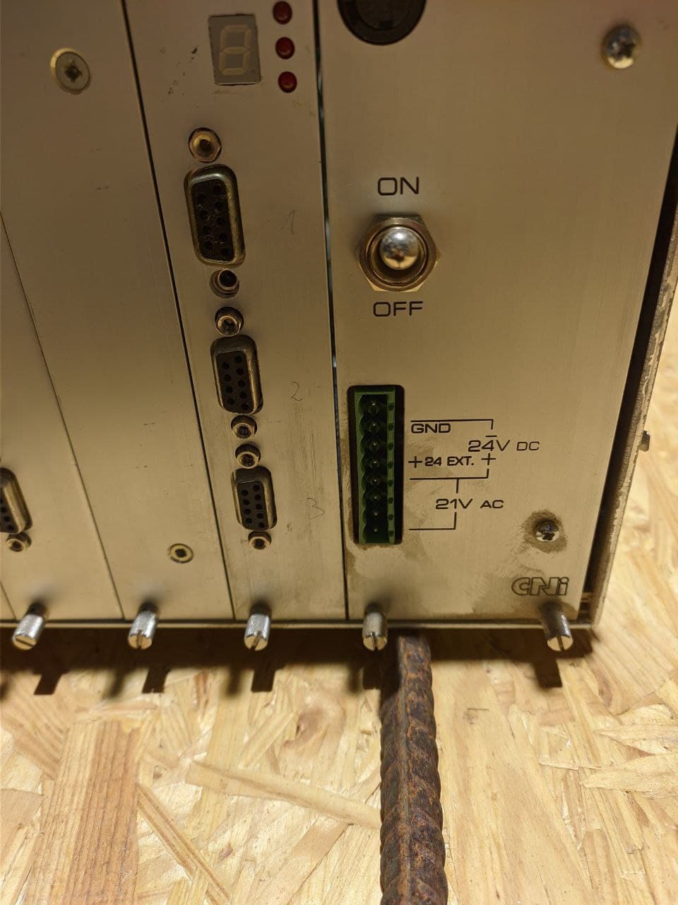
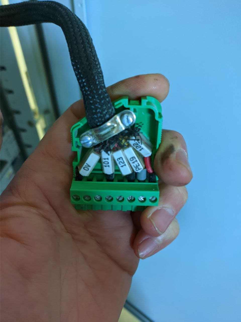
Still trying to wrap my head around the labeling of the power supply, why there is 21 V AC and what some things in the schematics are. I'll need to have a fresh look tomorrow, at the machine. I've been staring at page 43 of the schematics for a while...
Re: modules in the cabinet (which both have relays outputs): I already have some Finder DIN rail relays, they work nicely with the Mesa cards (tested).
On another note, the 7i77 looks great in there
Attachments:
Please Log in or Create an account to join the conversation.
- tray
- Offline
- Junior Member
-

Less
More
- Posts: 26
- Thank you received: 3
09 Sep 2022 09:28 #251536
by tray
Replied by tray on topic Another Biesse Rover 322
Hi,
I too have a 322 building in MESA 7I76 and 7I77 to replace the controller
Did you conclude what the 21V AC was for?
I too have a 322 building in MESA 7I76 and 7I77 to replace the controller
Did you conclude what the 21V AC was for?
Please Log in or Create an account to join the conversation.
- tray
- Offline
- Junior Member
-

Less
More
- Posts: 26
- Thank you received: 3
09 Sep 2022 09:35 #251537
by tray
Replied by tray on topic Another Biesse Rover 322
I have attached an inkscape file with labels for the mesa boards (7I76 7I77) if anyone is interested. Print them out as A4, and attached to the green and orange plugs on the board.
Please Log in or Create an account to join the conversation.
- tray
- Offline
- Junior Member
-

Less
More
- Posts: 26
- Thank you received: 3
09 Sep 2022 09:41 #251538
by tray
Replied by tray on topic Another Biesse Rover 322
My understanding is
P1 is 24V when machine is powered on.
P2, P3, P4 are on based on the condition of the Emergency Device E22 (see columns 14-16 of the drawings)
The Mesa manuals advise not to use power through switching devices.
P1 is 24V when machine is powered on.
P2, P3, P4 are on based on the condition of the Emergency Device E22 (see columns 14-16 of the drawings)
The Mesa manuals advise not to use power through switching devices.
Please Log in or Create an account to join the conversation.
- tommylight
-

- Online
- Moderator
-

Less
More
- Posts: 21301
- Thank you received: 7274
09 Sep 2022 10:10 #251540
by tommylight
Replied by tommylight on topic Another Biesse Rover 322
What drawing?

Please Log in or Create an account to join the conversation.
Time to create page: 0.146 seconds

