Program exceeds machine limits error using G33 (in 2.7.0~pre7)
- tome
- Offline
- Premium Member
-

Less
More
- Posts: 134
- Thank you received: 11
01 Sep 2015 11:51 #61978
by tome
Program exceeds machine limits error using G33 (in 2.7.0~pre7) was created by tome
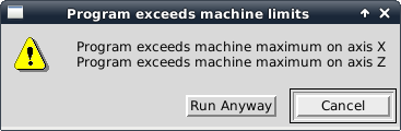
We get the error below when we try to run G33. The program runs if we select "Run Anyway" - it doesn't exceed the limits yet the error always comes up. What would cause this?
Here is an example of code that causes it:
;
; score a workpiece, n times around its circumference
;
#<workDiameter> = 0.75
#<safeXOffset> = 0.025
#<workRadius> = [ #<workDiameter>/2 ]
#<safeX> = [#<workRadius> + #<safeXOffset>]
#<startZ> = -0.300
#<depthOfCut> = 0.005
#<numberOfCuts> = 2
; need to feed twice (in _and_ out) the depth of cut *
; <numberOfCuts> per revolution
#<radialFeedRate> = [2 * #<depthOfCut> * #<numberOfCuts>]
(debug, radial feed rate: #<radialFeedRate>)
G8
M4 S100
G0 X#<safeX>
G0 Z#<startZ>
G1 X#<workRadius> F5
#100 = #<numberOfCuts>
o100 WHILE [#100 GT 0]
G33 X[#<workRadius> - #<depthOfCut>] K#<radialFeedRate> (feed in)
G33 X#<workRadius> K#<radialFeedRate> (feed out)
#100 = [#100 - 1]
o100 ENDWHILE
G0 X#<safeX>
G0 Z#<startZ>
M5
M2
Please Log in or Create an account to join the conversation.
- BigJohnT
-

- Offline
- Administrator
-

Less
More
- Posts: 7000
- Thank you received: 1176
01 Sep 2015 19:01 #61989
by BigJohnT
Replied by BigJohnT on topic Program exceeds machine limits error using G33 (in 2.7.0~pre7)
That code does not cause an error when run in the Axis lathe sim. Check to see if you have some G92 offsets left over from another program.
JT
JT
Please Log in or Create an account to join the conversation.
- tome
- Offline
- Premium Member
-
Less
More
- Posts: 134
- Thank you received: 11
01 Sep 2015 20:20 #61993
by tome
Nope, no G92 offsets in place...
Replied by tome on topic Program exceeds machine limits error using G33 (in 2.7.0~pre7)
That code does not cause an error when run in the Axis lathe sim. Check to see if you have some G92 offsets left over from another program.
JT
Nope, no G92 offsets in place...
Please Log in or Create an account to join the conversation.
- tome
- Offline
- Premium Member
-
Less
More
- Posts: 134
- Thank you received: 11
01 Sep 2015 20:28 #61995
by tome
Replied by tome on topic Program exceeds machine limits error using G33 (in 2.7.0~pre7)
It doesn't seem to be a position problem because when commanded to run regardless, it moves to the workpiece and takes light cuts as expected.
It shouldn't be a feed rate problem either. In the code, it is asked to move 0.005" 4 times in a single revolution. That's 0.02" in total. And at 100 rpm, that's only 2 ipm.
It is being asked to reverse direction so the trajectory planner could be throwing up its hands? But that doesn't explain why it complains about the Z axis in addition to X; there aren't many Z moves in it and there are no Z movements in G33.
My configs are attached if that gives a clue...
Please Log in or Create an account to join the conversation.
- BigJohnT
-
- Offline
- Administrator
-
Less
More
- Posts: 7000
- Thank you received: 1176
01 Sep 2015 21:07 #61997
by BigJohnT
Replied by BigJohnT on topic Program exceeds machine limits error using G33 (in 2.7.0~pre7)
You have max limits of 0.001 for both axes, when I run the program in the simulator the X axis ends up at 0.400 which is greater than 0.001 so I would expect and error but how it runs for you is unknown to me. Your not selecting a tool in your G code so I assume your doing some touch off before running? Seems to me the last line should be G) Z#<safeZ> but you don't define that.
JT
JT
Please Log in or Create an account to join the conversation.
- cncbasher
- Offline
- Moderator
-

Less
More
- Posts: 1744
- Thank you received: 288
01 Sep 2015 22:38 #62007
by cncbasher
Replied by cncbasher on topic Program exceeds machine limits error using G33 (in 2.7.0~pre7)
for me the z axis is wrong ?
MIN_LIMIT = -2.106
MAX_LIMIT = 0.001
this is a lathe yes , so ok you have reversed the stepper drive to get the motors running in the correct direction , i would prefer to have the software correct and
reverse the stepper motor wires so the sense of the software is correct , in a sense you have ferror as 1 where it should be -1 to have the same sense
these ferror limits you have set , are just not obtainable using stepper motors .
you just dont need them for steppers , so the ferror etc are pure software calculation , and cant be relied on in real life as theirs no feedback
i'd open the max limit to 0.2 .
it's far better to match the machine to the run in the correct sense , even if it means rewiring a stepper driver to do it , then at least the calculations will run the correct way
this can catch you out for instance on a spindle when screw cutting .
be a bit more conservative with values and the problem you have should go away .
Please Log in or Create an account to join the conversation.
- tome
- Offline
- Premium Member
-
Less
More
- Posts: 134
- Thank you received: 11
02 Sep 2015 00:45 - 02 Sep 2015 01:10 #62016
by tome
I think it is the 0.001 max limit that is causing it, but if I set it larger, to say 0.5 or higher don't I run the risk of sending my axis beyond it's zero point? This is a back tool lathe and my as such moves from X=0 to X= -2.1 and Z=0 to Z= -7 (or thereabouts). Doesn't setting MAX_LIMIT to 0.5 mean it can move back beyond it's home (zero) point in a program?
The program I posted doesn't do tool loading as we just did a simplified example of the issue. We loaded tool 1 and touched it off outside the program and it doesn't end up a 0.400 (or anywhere outside our limits).
-Tom
ps: I retract the above statement. I DON'T think the max limit is the culprit. After loading our tool #1 we don't go anywhere near any of the limits. Also, my machine cannot physically move more than a small amount beyond the home point (zero) so I cannot set MAX_LIMIT more than a few thou and be safe. I think this is a red herring.
Replied by tome on topic Program exceeds machine limits error using G33 (in 2.7.0~pre7)
You have max limits of 0.001 for both axes, when I run the program in the simulator the X axis ends up at 0.400 which is greater than 0.001 so I would expect and error but how it runs for you is unknown to me. Your not selecting a tool in your G code so I assume your doing some touch off before running? Seems to me the last line should be G) Z#<safeZ> but you don't define that.
JT
I think it is the 0.001 max limit that is causing it, but if I set it larger, to say 0.5 or higher don't I run the risk of sending my axis beyond it's zero point? This is a back tool lathe and my as such moves from X=0 to X= -2.1 and Z=0 to Z= -7 (or thereabouts). Doesn't setting MAX_LIMIT to 0.5 mean it can move back beyond it's home (zero) point in a program?
The program I posted doesn't do tool loading as we just did a simplified example of the issue. We loaded tool 1 and touched it off outside the program and it doesn't end up a 0.400 (or anywhere outside our limits).
-Tom
ps: I retract the above statement. I DON'T think the max limit is the culprit. After loading our tool #1 we don't go anywhere near any of the limits. Also, my machine cannot physically move more than a small amount beyond the home point (zero) so I cannot set MAX_LIMIT more than a few thou and be safe. I think this is a red herring.
Last edit: 02 Sep 2015 01:10 by tome.
Please Log in or Create an account to join the conversation.
- tome
- Offline
- Premium Member
-
Less
More
- Posts: 134
- Thank you received: 11
02 Sep 2015 00:56 - 02 Sep 2015 00:59 #62018
by tome
I guess I am not sure what "correct sense" means to you, or how that would change how the UI works now - which has been fine. This is a back-tool lathe and from everything I read setting this up I do have it configured to act correctly for that configuration. I don't know how I would rewire my 5-phase stepper motors to change anything. It took me several iterations to get them wired to work correctly, I'd certainly rather not try to re-wire them...
But you say my ferror should be -1 (rather than 1), is that true? Also, you say my ferror limits are not obtainable. I think those values are from pncconf wizard, I don't think I configured them. I'm not really sure what they should be, do you have more realistic values I should use? Or are you saying I should just remove them from the config entirely?
Thanks,
-Tom
ps: We have cut a bunch of threads and they have come out great, not sure how the config can cause a problem here...?
Replied by tome on topic Program exceeds machine limits error using G33 (in 2.7.0~pre7)
for me the z axis is wrong ?
MIN_LIMIT = -2.106
MAX_LIMIT = 0.001
this is a lathe yes , so ok you have reversed the stepper drive to get the motors running in the correct direction , i would prefer to have the software correct and
reverse the stepper motor wires so the sense of the software is correct , in a sense you have ferror as 1 where it should be -1 to have the same sense
these ferror limits you have set , are just not obtainable using stepper motors .
you just dont need them for steppers , so the ferror etc are pure software calculation , and cant be relied on in real life as theirs no feedback
i'd open the max limit to 0.2 .
it's far better to match the machine to the run in the correct sense , even if it means rewiring a stepper driver to do it , then at least the calculations will run the correct way
this can catch you out for instance on a spindle when screw cutting .
be a bit more conservative with values and the problem you have should go away .
I guess I am not sure what "correct sense" means to you, or how that would change how the UI works now - which has been fine. This is a back-tool lathe and from everything I read setting this up I do have it configured to act correctly for that configuration. I don't know how I would rewire my 5-phase stepper motors to change anything. It took me several iterations to get them wired to work correctly, I'd certainly rather not try to re-wire them...
But you say my ferror should be -1 (rather than 1), is that true? Also, you say my ferror limits are not obtainable. I think those values are from pncconf wizard, I don't think I configured them. I'm not really sure what they should be, do you have more realistic values I should use? Or are you saying I should just remove them from the config entirely?
Thanks,
-Tom
ps: We have cut a bunch of threads and they have come out great, not sure how the config can cause a problem here...?
Last edit: 02 Sep 2015 00:59 by tome.
Please Log in or Create an account to join the conversation.
- BigJohnT
-
- Offline
- Administrator
-
Less
More
- Posts: 7000
- Thank you received: 1176
02 Sep 2015 02:56 #62024
by BigJohnT
Can you elaborate on how you loaded the tool and touched off? Does this lathe have a turret and use the tool table?
And no, you don't want to set the limits outside the physical limits.
JT
Replied by BigJohnT on topic Program exceeds machine limits error using G33 (in 2.7.0~pre7)
The program I posted doesn't do tool loading as we just did a simplified example of the issue. We loaded tool 1 and touched it off outside the program and it doesn't end up a 0.400 (or anywhere outside our limits).
-Tom
Can you elaborate on how you loaded the tool and touched off? Does this lathe have a turret and use the tool table?
And no, you don't want to set the limits outside the physical limits.
JT
Please Log in or Create an account to join the conversation.
- tome
- Offline
- Premium Member
-
Less
More
- Posts: 134
- Thank you received: 11
02 Sep 2015 09:32 #62037
by tome
The lathe has a turret. We do M6 T1 which loads the tool and also set tool length offset (G43 I think). A button in Glade side panel for each tool runs a script actually. Tools are first touched off to a fixture (wired to Mesa 7i84 input) that is mounted on the spindle head in both Z and X (using G38.something). Then tool 1 is set to the end of workpiece and Z is touched off (G54) and then set on known diameter (or radius since we usually have G8 set) and X is touched off (G54 again).
Tom
Replied by tome on topic Program exceeds machine limits error using G33 (in 2.7.0~pre7)
Can you elaborate on how you loaded the tool and touched off? Does this lathe have a turret and use the tool table?
The lathe has a turret. We do M6 T1 which loads the tool and also set tool length offset (G43 I think). A button in Glade side panel for each tool runs a script actually. Tools are first touched off to a fixture (wired to Mesa 7i84 input) that is mounted on the spindle head in both Z and X (using G38.something). Then tool 1 is set to the end of workpiece and Z is touched off (G54) and then set on known diameter (or radius since we usually have G8 set) and X is touched off (G54 again).
Tom
Please Log in or Create an account to join the conversation.
Time to create page: 0.081 seconds