Strange behaviour - thought it was X axis problem but not sure?
- uptown47
- Offline
- Senior Member
-

Less
More
- Posts: 48
- Thank you received: 1
05 Dec 2018 22:03 - 05 Dec 2018 22:08 #121907
by uptown47
Strange behaviour - thought it was X axis problem but not sure? was created by uptown47
Hi there,
I'm busy setting up my own home-made CNC machine.
I thought I had a problem with my X axis drifting so I've been doing some experimenting.
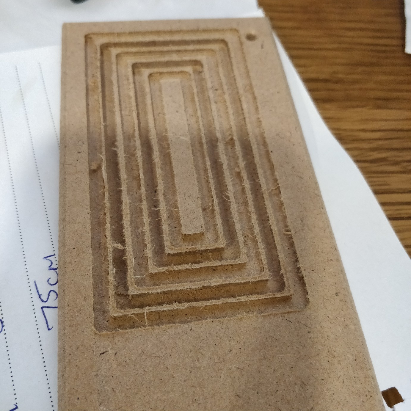
I made the following concentric rectangles earlier and used a 3mm End Mill on them.
I ran two different tool paths (albeit using the same tool) and they came out (in my untrained eye) excellently.
I then made a small sign up (these blanks are only 150mm x 70mm).
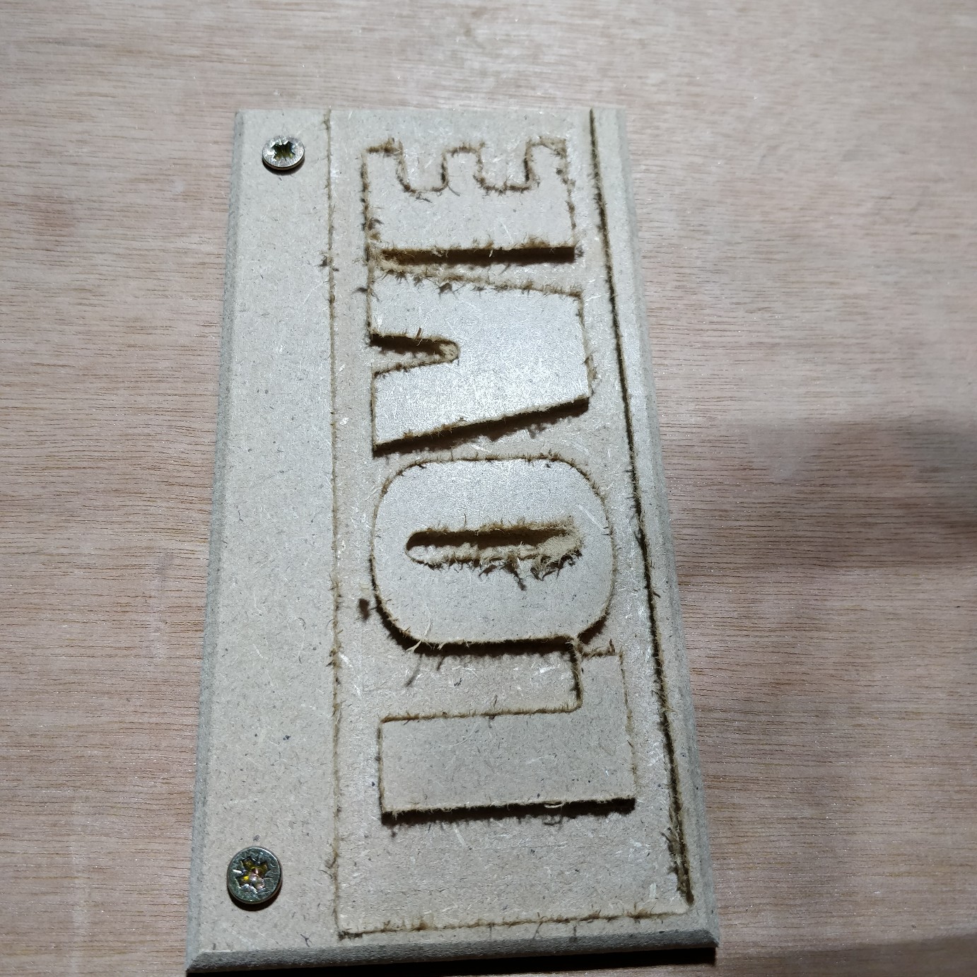
I set up two toolpaths. One using a 3mm End Mill again which created this.....
And then another running after this one using a 2mm Ball Nose. It might be worth noting that there wasn't a 2mm Ball Nose in the software so I added it with the following parameters (I am clueless at the moment regarding feed rates etc as I'm completely new to CNC but I took most of the settings from the 3mm Ball Nose and just lowered them slightly).

After running the 2mm Ball Nose it messed the carving up...
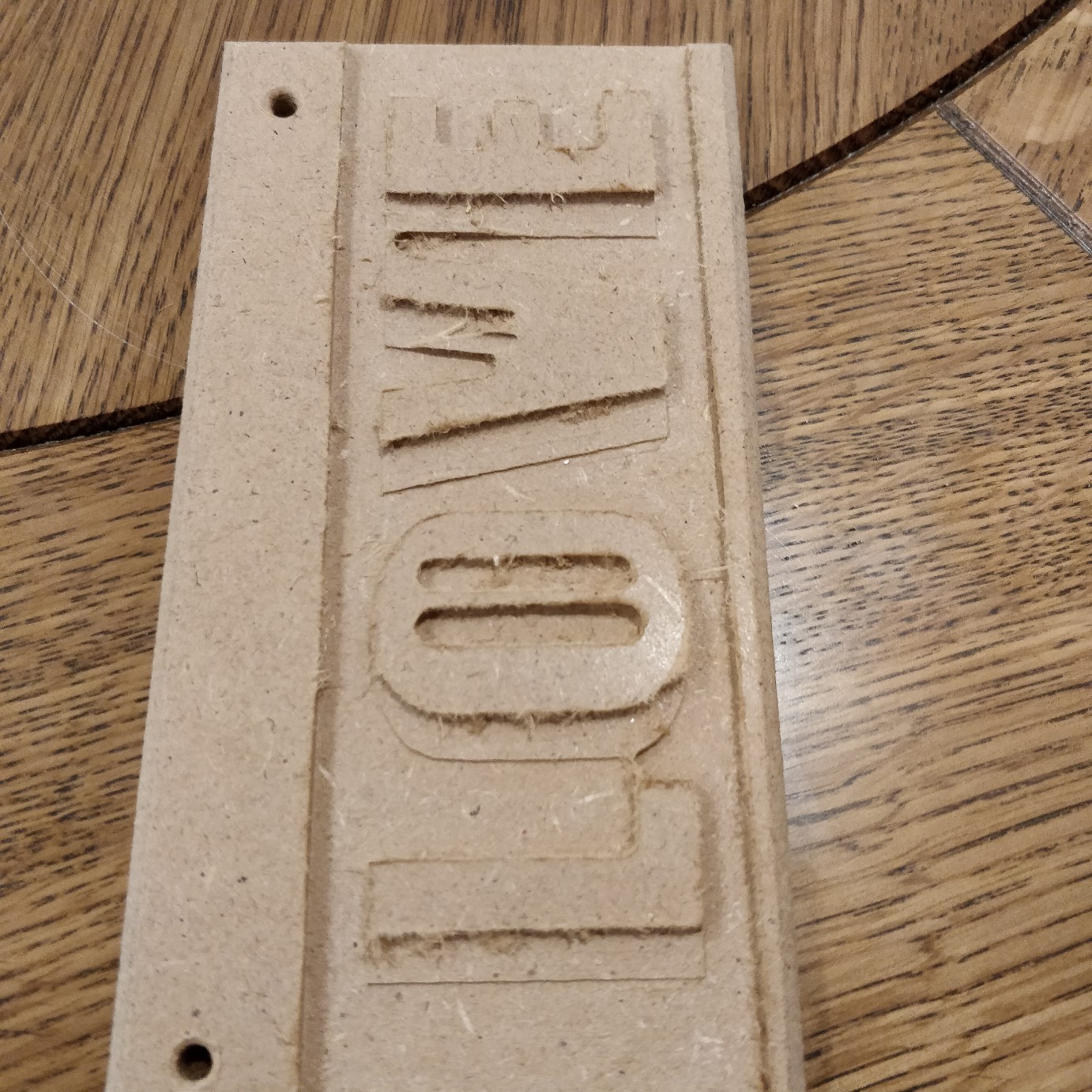
You can see in that last image it is as though the whole thing has moved over to the right?
(It's worth noting that the wood was screwed into the machine through those holes with the long edge as the X axis. I just took the photos from that angle as I thought you could see where the tool has cut the wrong parts better)
I'm really stuck as to why this is happening?
I would have thought that if the machine was running out of position it would have done it during the concentric rectangles or the initial carving of the word "LOVE".
I've obviously got something amiss with either the machine or the settings and I just wondered if anyone knew what things could cause this? And what (if anything) I can do to fix it and (ideally) keep it fixed.
A massive thank you for any light you can shed on this as I've come to the end of my ideas and I'm now well and truly stuck.
Thanks")
PS. Also while I'm here - could you just confirm that, when cutting these MDF blanks, you are suppose to get that 'tearing' around the edges? Or is that excessive? If so, how do I reduce it?
I'm busy setting up my own home-made CNC machine.
I thought I had a problem with my X axis drifting so I've been doing some experimenting.
I made the following concentric rectangles earlier and used a 3mm End Mill on them.
I ran two different tool paths (albeit using the same tool) and they came out (in my untrained eye) excellently.
I then made a small sign up (these blanks are only 150mm x 70mm).
I set up two toolpaths. One using a 3mm End Mill again which created this.....
And then another running after this one using a 2mm Ball Nose. It might be worth noting that there wasn't a 2mm Ball Nose in the software so I added it with the following parameters (I am clueless at the moment regarding feed rates etc as I'm completely new to CNC but I took most of the settings from the 3mm Ball Nose and just lowered them slightly).
After running the 2mm Ball Nose it messed the carving up...
You can see in that last image it is as though the whole thing has moved over to the right?
(It's worth noting that the wood was screwed into the machine through those holes with the long edge as the X axis. I just took the photos from that angle as I thought you could see where the tool has cut the wrong parts better)
I'm really stuck as to why this is happening?
I would have thought that if the machine was running out of position it would have done it during the concentric rectangles or the initial carving of the word "LOVE".
I've obviously got something amiss with either the machine or the settings and I just wondered if anyone knew what things could cause this? And what (if anything) I can do to fix it and (ideally) keep it fixed.
A massive thank you for any light you can shed on this as I've come to the end of my ideas and I'm now well and truly stuck.
Thanks
PS. Also while I'm here - could you just confirm that, when cutting these MDF blanks, you are suppose to get that 'tearing' around the edges? Or is that excessive? If so, how do I reduce it?
Last edit: 05 Dec 2018 22:08 by uptown47.
Please Log in or Create an account to join the conversation.
- Todd Zuercher
-

- Away
- Platinum Member
-

Less
More
- Posts: 4764
- Thank you received: 1464
06 Dec 2018 03:37 #121921
by Todd Zuercher
Replied by Todd Zuercher on topic Strange behaviour - thought it was X axis problem but not sure?
First thing to do is to look carefully at the g-code for both files to be sure they are carving in the same position. Then check to see if there are any offsets causing the problem. If you had to home the machine between runs and you don't have home switches, not having a fixed repeatable home position could cause this.
The following user(s) said Thank You: uptown47
Please Log in or Create an account to join the conversation.
- uptown47
- Offline
- Senior Member
-
Less
More
- Posts: 48
- Thank you received: 1
06 Dec 2018 09:04 #121935
by uptown47
Replied by uptown47 on topic Strange behaviour - thought it was X axis problem but not sure?
Hi Todd
Thanks (again) for helping me. It's really appreciated.
I only homed the machine the first time.
I then did an End Mill carve and the machine went back to the original home position.
I then loaded the next carve (the ball nose) and changed the bit (ensuring the bit stuck out of the spindle by the same amount as the End Mill) and just pressed 'run'.
The carving was exactly the same image. I just chose the "Pocket" option using the end mill and saved that toolpath. I then chose the Pocket option using the ball nose and saved that.
This same issue also happened on an earlier carving I did that *only* used the ball nose. I again had written some letters and then told the software to pocket it out. It seemed to be working well on the first pass but then starting eating away at the already carved letters on the next passes.
I wondered about a mechanical issue but then it seemed to work fine for the End Mill (albeit with just one pass).
I maybe need to try the End Mill with a 3mm carve depth and just 1mm per pass to see if messes itself up that way?
I'm away on holiday tonight so won't get to play with it until next Thursday when I get back.
If there's anything else you can think that would cause this I'm all ears.
Cheers
John
Please Log in or Create an account to join the conversation.
- Todd Zuercher
-
- Away
- Platinum Member
-
Less
More
- Posts: 4764
- Thank you received: 1464
06 Dec 2018 13:59 #121951
by Todd Zuercher
Replied by Todd Zuercher on topic Strange behaviour - thought it was X axis problem but not sure?
It is possible you might be loosing steps on rapid moves in the X axis?
Could you post your g-code files?
Are you using incremental or absolute mode (G90/G91) in your code?
There are other g-codes that could be potentially messing you up. (Hence why you should post your g-code files.)
Could you post your g-code files?
Are you using incremental or absolute mode (G90/G91) in your code?
There are other g-codes that could be potentially messing you up. (Hence why you should post your g-code files.)
The following user(s) said Thank You: uptown47
Please Log in or Create an account to join the conversation.
- andypugh
-

- Offline
- Moderator
-

Less
More
- Posts: 19879
- Thank you received: 4644
06 Dec 2018 15:01 #121952
by andypugh
Replied by andypugh on topic Strange behaviour - thought it was X axis problem but not sure?
Is it possible you have an X offset in your Tool Table for one or more tools?
The following user(s) said Thank You: tommylight, uptown47
Please Log in or Create an account to join the conversation.
- uptown47
- Offline
- Senior Member
-
Less
More
- Posts: 48
- Thank you received: 1
06 Dec 2018 15:58 #121956
by uptown47
Replied by uptown47 on topic Strange behaviour - thought it was X axis problem but not sure?
Todd, I've attached my .ngc files here for both the rough (LOVE_1.ngc) and the fine (LOVE_2.ngc) toolpaths.
That's a good point Andy? I'm not sure. I'm using Aspire and I've looked in the Tool menu and can't find anything to do with an offset?
Do you know where that setting would be? I'm brand new to Aspire so still finding my way around the software and working through the YouTube tutorials.
That's a good point Andy? I'm not sure. I'm using Aspire and I've looked in the Tool menu and can't find anything to do with an offset?
Do you know where that setting would be? I'm brand new to Aspire so still finding my way around the software and working through the YouTube tutorials.
Please Log in or Create an account to join the conversation.
- andypugh
-
- Offline
- Moderator
-
Less
More
- Posts: 19879
- Thank you received: 4644
06 Dec 2018 16:55 #121957
by andypugh
Replied by andypugh on topic Strange behaviour - thought it was X axis problem but not sure?
I am talking about the LinuxCNC tool table.
(probably in your config folder, and called "tool.tbl")
Most LinuxCNC GUIs have a menu item "edit tool table". Open that and make sure that the X and Y offsets for every tool are zero. (It is very unlikely that any rotating-tool machine will need X or Y offsets, they exist for plasma, laser, lathe etc.
The following user(s) said Thank You: uptown47
Please Log in or Create an account to join the conversation.
- uptown47
- Offline
- Senior Member
-
Less
More
- Posts: 48
- Thank you received: 1
06 Dec 2018 17:02 #121958
by uptown47
Thanks for that Andy. I've just set off on my holiday and won't be back home until Thursday but will certainly check then. I've not changed anything like that though and, on a previous carve with only the 2mm Ball Nose, it started correctly and then cut through the letters on the next pass so I'm guessing any offset would be consistent?
However, I will check when I get back just to rule it out.
I've also ordered a 3mm ball nose today as my software has that bit pre-programmed into it so I'll try that when I get it and see if it behaves the same way.
In the meantime, any other ideas are more than welcome for me to try and rule things in or out as the source of the problem.
Cheers
John
Replied by uptown47 on topic Strange behaviour - thought it was X axis problem but not sure?
I am talking about the LinuxCNC tool table.
(probably in your config folder, and called "tool.tbl")
Most LinuxCNC GUIs have a menu item "edit tool table". Open that and make sure that the X and Y offsets for every tool are zero. (It is very unlikely that any rotating-tool machine will need X or Y offsets, they exist for plasma, laser, lathe etc.
Thanks for that Andy. I've just set off on my holiday and won't be back home until Thursday but will certainly check then. I've not changed anything like that though and, on a previous carve with only the 2mm Ball Nose, it started correctly and then cut through the letters on the next pass so I'm guessing any offset would be consistent?
However, I will check when I get back just to rule it out.
I've also ordered a 3mm ball nose today as my software has that bit pre-programmed into it so I'll try that when I get it and see if it behaves the same way.
In the meantime, any other ideas are more than welcome for me to try and rule things in or out as the source of the problem.
Cheers
John
Please Log in or Create an account to join the conversation.
- Todd Zuercher
-
- Away
- Platinum Member
-
Less
More
- Posts: 4764
- Thank you received: 1464
06 Dec 2018 17:28 #121967
by Todd Zuercher
Replied by Todd Zuercher on topic Strange behaviour - thought it was X axis problem but not sure?
The tool offsets are saved in the tool table of Linuxcnc, but that shouldn't have been your problem because the g-code files are using the same tool offsets (unless you changed them between runs. (You didn't do any touch off or tool touch off between runs did you?) If you did a touch off of some kind between runs, a mistake there could have caused it.
The files look to be in the same positions.
You changed tools between runs, Did you have the motors disabled while you were changing tools? If you did, you could have easily moved the machine's position while wrenching on the spindle to change tools.
There is still the possibility of a mechanical issue, a slipping coupling, lost steps, or you forced the spindle to move while changing tools.
As to your fuzzing problem milling the MDF, to some extent it is just the nature of the beast. MDF can be very hard on tooling. Different kinds of MDF from different sources mill nicer than others. (The MDF in your photos looks to be of the less nice variety.) Only use carbide tooling if possible for MDF (steel will dull very quickly), but to minimize fuzzing use very sharp carbide tooling with no more than 2 flutes (cutting edges). We use a lot of PCD (diamond) tipped tools for MDF, but they are expensive and only come in larger tool sizes. Use the largest diameter tool possible for the job. Keep your chip load high (about 40mm/sec for a 3mm tool at 16000rpm is a decent speed.) Don't cut deeper than about twice the diameter of the tool in a single pass, when cutting a slot (finish passes can usually use the full cutting length of the tool).
The following user(s) said Thank You: uptown47
Please Log in or Create an account to join the conversation.
- uptown47
- Offline
- Senior Member
-
Less
More
- Posts: 48
- Thank you received: 1
06 Dec 2018 19:29 #121983
by uptown47
Replied by uptown47 on topic Strange behaviour - thought it was X axis problem but not sure?
That's great info Todd. The motors were definitely locked when I changed tools and nothing moved at all. I didn't touch off etc between tool changes.
It must be losing steps somehow. I wondered about electrical noise. When I get back from holiday I might try and set up a simple carving of a series of holes and try and keep repeating them to see what happens.
A massive thanks for the info on tools and speeds. I really need that kind of info and I really appreciate you taking the time to write all that. Brilliant. Cheers
John
Please Log in or Create an account to join the conversation.
Time to create page: 0.179 seconds