Wires detached from parallel plug
- ictponder
- Offline
- Junior Member
-

Less
More
- Posts: 23
- Thank you received: 0
10 Jun 2019 19:07 #136503
by ictponder
Replied by ictponder on topic Wires detached from parallel plug
TY for the pinout guide. I found a picture in the linuxcnc.org archive but it looked way different. I've attached the original file if it helps.
Attachments:
Please Log in or Create an account to join the conversation.
- andypugh
-

- Offline
- Moderator
-

Less
More
- Posts: 19886
- Thank you received: 4645
10 Jun 2019 19:18 #136504
by andypugh
Replied by andypugh on topic Wires detached from parallel plug
It looks like there are no limits enabled.
I would suggest that the intention might have been for the limit to be a debounced version of the home (this makes some sense, as nusciance tripping is annoying, and 10mS delay on hitting the limit is unlikely to matter that much)
There is already a debounce.0.1 available, you could use that. (though it has the same 100mS debounce time as the probe. Which seems a bit long for a probe, too)
Please Log in or Create an account to join the conversation.
- PCW
-

- Online
- Moderator
-
Less
More
- Posts: 17995
- Thank you received: 5281
10 Jun 2019 19:32 #136506
by PCW
Replied by PCW on topic Wires detached from parallel plug
It looks like the debounce is addf-ed to the base-thread so the time
will be quite a bit shorter than 100 ms
will be quite a bit shorter than 100 ms
Please Log in or Create an account to join the conversation.
- andypugh
-
- Offline
- Moderator
-
Less
More
- Posts: 19886
- Thank you received: 4645
10 Jun 2019 19:39 #136507
by andypugh
Replied by andypugh on topic Wires detached from parallel plug
Ah, right.
That probably makes some sense, debouncing in the fast thread and servicing in the slow one.
That probably makes some sense, debouncing in the fast thread and servicing in the slow one.
Please Log in or Create an account to join the conversation.
- ictponder
- Offline
- Junior Member
-
Less
More
- Posts: 23
- Thank you received: 0
10 Jun 2019 21:40 #136515
by ictponder
Replied by ictponder on topic Wires detached from parallel plug
I noticed that the limit switches are, for the most part, daisy chained together ie: COM leg from one switch connected to NC leg from another switch behind the parallel plug.
Please Log in or Create an account to join the conversation.
- PCW
-
- Online
- Moderator
-
Less
More
- Posts: 17995
- Thank you received: 5281
10 Jun 2019 21:55 - 10 Jun 2019 21:55 #136516
by PCW
Replied by PCW on topic Wires detached from parallel plug
Yeah shared switches because of likely running out of pins for
limit/home inputs.
Since there are no limit switch connections in the hal file you are free to connect
the common limit/home signal to any free parallel port input (say pin 11 or 13...)
limit/home inputs.
Since there are no limit switch connections in the hal file you are free to connect
the common limit/home signal to any free parallel port input (say pin 11 or 13...)
Last edit: 10 Jun 2019 21:55 by PCW.
The following user(s) said Thank You: ictponder
Please Log in or Create an account to join the conversation.
- ictponder
- Offline
- Junior Member
-
Less
More
- Posts: 23
- Thank you received: 0
11 Jun 2019 00:16 #136521
by ictponder
Replied by ictponder on topic Wires detached from parallel plug
So one side of the chain to ground and the other side to one of the input pins?
Please Log in or Create an account to join the conversation.
- tommylight
-

- Away
- Moderator
-
Less
More
- Posts: 21763
- Thank you received: 7437
11 Jun 2019 02:02 #136527
by tommylight
Replied by tommylight on topic Wires detached from parallel plug
Yes.
Please Log in or Create an account to join the conversation.
- ictponder
- Offline
- Junior Member
-
Less
More
- Posts: 23
- Thank you received: 0
11 Jun 2019 02:54 - 11 Jun 2019 02:56 #136532
by ictponder
Replied by ictponder on topic Wires detached from parallel plug
Very good, that should help me understand what's going on a little better as I assumed each limit switch was isolated.
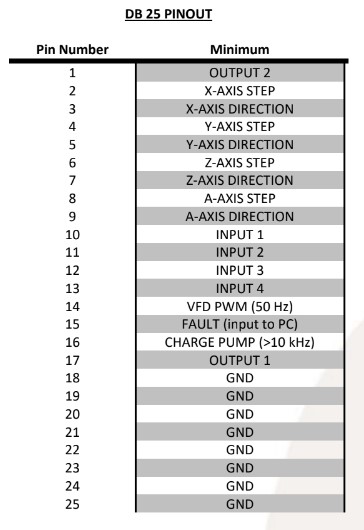
I found this image in a manual for a gecko drive a friend sent me that shows the pinout for that system and I wondered if the parallel plug is always going to be the same no matter what other than changing the axis labels? I've also got my VFD connected via USB directly to the computer, not the parallel plug. I've attached the image.
I found this image in a manual for a gecko drive a friend sent me that shows the pinout for that system and I wondered if the parallel plug is always going to be the same no matter what other than changing the axis labels? I've also got my VFD connected via USB directly to the computer, not the parallel plug. I've attached the image.
Attachments:
Last edit: 11 Jun 2019 02:56 by ictponder.
Please Log in or Create an account to join the conversation.
- andypugh
-
- Offline
- Moderator
-
Less
More
- Posts: 19886
- Thank you received: 4645
11 Jun 2019 11:06 - 11 Jun 2019 11:08 #136583
by andypugh
If it's a Gecko with a DB25 then it must be a G540?
Yes, the pinout of the G540 is entirely standard for a G540, but may not match anything else.
It might be worth knowing that there is a firmware for the 5i25 / 6i25 PCI cards for the G540 if you find that you run out of step rate with the parallel port.
You might also find that the charge-pump input can't be driven by your parport except in EPP mode (BIOS setting) and possibly not even then. The charge pump can be disabled, but obviously it would be better not to.
I now see that you were showing the Gecko pinout purely as an example. No, there is no standard for how a paralel port is wired to drives, you can do it any way that is convenient.
Replied by andypugh on topic Wires detached from parallel plug
Yes, the pinout of the G540 is entirely standard for a G540, but may not match anything else.
It might be worth knowing that there is a firmware for the 5i25 / 6i25 PCI cards for the G540 if you find that you run out of step rate with the parallel port.
You might also find that the charge-pump input can't be driven by your parport except in EPP mode (BIOS setting) and possibly not even then. The charge pump can be disabled, but obviously it would be better not to.
I now see that you were showing the Gecko pinout purely as an example. No, there is no standard for how a paralel port is wired to drives, you can do it any way that is convenient.
Last edit: 11 Jun 2019 11:08 by andypugh.
Please Log in or Create an account to join the conversation.
Time to create page: 0.108 seconds