- LinuxCNC
- General LinuxCNC Questions
- China- BoB grounding questions; how to correctly power the board
China- BoB grounding questions; how to correctly power the board
- Louis Cypher
- Offline
- Senior Member
-

Less
More
- Posts: 45
- Thank you received: 0
20 Aug 2019 12:22 #142592
by Louis Cypher
China- BoB grounding questions; how to correctly power the board was created by Louis Cypher
I fried my chinese CNC- breakoutboard by letting my machine run for about 4 hours without moving the drives. Very likely it was a grounding problem.
My Setup:
- BoB connected to PC via LPT
- BoB powered via USB cable from PC
- PC not grounded to my CNC electronics.
- BoB Inputs powered by an external powersupply on 12V; ground not connected to any other ground. I think this fried the board. Only possible if the input circuit has no ground connection to the rest of the board, right?
- Drivers connected to a Chinese 36V powersupply. DC ground and AC ground connected
I think the potential of the Input- Circuit powersupply drifted away from the powersupply of the PC or the powersupply of the drivers. My questions are pretty obvious:
Thanks in advance for your appreciated help.
My Setup:
- BoB connected to PC via LPT
- BoB powered via USB cable from PC
- PC not grounded to my CNC electronics.
- BoB Inputs powered by an external powersupply on 12V; ground not connected to any other ground. I think this fried the board. Only possible if the input circuit has no ground connection to the rest of the board, right?
- Drivers connected to a Chinese 36V powersupply. DC ground and AC ground connected
I think the potential of the Input- Circuit powersupply drifted away from the powersupply of the PC or the powersupply of the drivers. My questions are pretty obvious:
- How should the Inputs be powered? I am planning to put a step down converter on the 36V PS
- How is the grounding concept for the PC? In the documentation I read that PC ground and PS ground should not be connected, but to me this is impossible since LPT has a ground Connection, Right?
- Should the Input supply voltage be grounded to the 5V?
- Should the 5V input of the BoB (USB connecter) perferably be supplied by a step down converter from 36V as well rather than via USB?
Thanks in advance for your appreciated help.
Please Log in or Create an account to join the conversation.
- pl7i92
-

- Offline
- Platinum Member
-

Less
More
- Posts: 1872
- Thank you received: 358
20 Aug 2019 14:41 #142599
by pl7i92
Replied by pl7i92 on topic China- BoB grounding questions; how to correctly power the board
is it the tb6560 you mean with china Bob
this boards dont like to be enabled without moving
therfor the pins of the enabled axis are always connected to the enable drive in linuxcnc and are disconnected
if it is the mach3 5axis bob
you may got the 12V-24V GND in a llop with the PC 5V
this is not recommended
this boards dont like to be enabled without moving
therfor the pins of the enabled axis are always connected to the enable drive in linuxcnc and are disconnected
if it is the mach3 5axis bob
you may got the 12V-24V GND in a llop with the PC 5V
this is not recommended
Please Log in or Create an account to join the conversation.
- Louis Cypher
- Offline
- Senior Member
-
Less
More
- Posts: 45
- Thank you received: 0
20 Aug 2019 22:57 - 20 Aug 2019 23:02 #142654
by Louis Cypher
Replied by Louis Cypher on topic China- BoB grounding questions; how to correctly power the board
thanks for the quick answering. Sorry I wasn't aware there are several BoBs on the market.
I have the mach3 5axis BoB (see picture). By saying it is not recommended you mean the board is not recommended? If you are referring to the wiring, how can I wire the board correctly. Should I preferably get the 5V and 12-24V from a step down converter connected to the main PSU? Doesn't the ground leep exist even in that case since LPT has a ground connected to the PC as well?
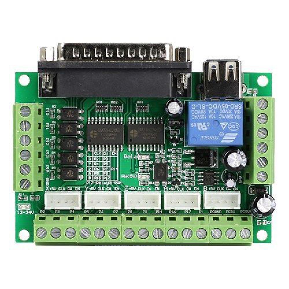
I have the mach3 5axis BoB (see picture). By saying it is not recommended you mean the board is not recommended? If you are referring to the wiring, how can I wire the board correctly. Should I preferably get the 5V and 12-24V from a step down converter connected to the main PSU? Doesn't the ground leep exist even in that case since LPT has a ground connected to the PC as well?
Attachments:
Last edit: 20 Aug 2019 23:02 by Louis Cypher. Reason: Added picture of board
Please Log in or Create an account to join the conversation.
- PCW
-

- Away
- Moderator
-

Less
More
- Posts: 17995
- Thank you received: 5282
20 Aug 2019 23:31 - 20 Aug 2019 23:31 #142656
by PCW
Replied by PCW on topic China- BoB grounding questions; how to correctly power the board
What fried?
I don't see any disadvantage of powering the 5V side from USB since the 5V common is PC ground anyway.
The inputs and analog section 12/24V is isolated from the PC so you can power these as you like.
I would not connect any of the input/analog common pins to PC ground
I don't see any disadvantage of powering the 5V side from USB since the 5V common is PC ground anyway.
The inputs and analog section 12/24V is isolated from the PC so you can power these as you like.
I would not connect any of the input/analog common pins to PC ground
Last edit: 20 Aug 2019 23:31 by PCW.
Please Log in or Create an account to join the conversation.
- Louis Cypher
- Offline
- Senior Member
-
Less
More
- Posts: 45
- Thank you received: 0
23 Aug 2019 14:25 - 23 Aug 2019 14:26 #142956
by Louis Cypher
Replied by Louis Cypher on topic China- BoB grounding questions; how to correctly power the board
I don't know yet because my machine and me are separated by 10.000km ") . I'll try to find out on Sunday evening.
. I'll try to find out on Sunday evening.
I'll check with a multimeter wether the grounds are seperated (which would make perfectly sense). Can a Floating 12-24V PSU with respect to the main PSU (36V) fry the board? I don't think those two grounds (drive electronics and Input Pins) are connected in my machine.
. I'll try to find out on Sunday evening.I'll check with a multimeter wether the grounds are seperated (which would make perfectly sense). Can a Floating 12-24V PSU with respect to the main PSU (36V) fry the board? I don't think those two grounds (drive electronics and Input Pins) are connected in my machine.
Last edit: 23 Aug 2019 14:26 by Louis Cypher. Reason: Missing information
Please Log in or Create an account to join the conversation.
- pl7i92
-
- Offline
- Platinum Member
-
Less
More
- Posts: 1872
- Thank you received: 358
23 Aug 2019 14:29 #142957
by pl7i92
Replied by pl7i92 on topic China- BoB grounding questions; how to correctly power the board
step down boards do work
i run a plasma with the 2 stepdowns and even with the EMI it workes fine Somtimes Mouse get lost
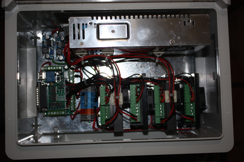
i run a plasma with the 2 stepdowns and even with the EMI it workes fine Somtimes Mouse get lost
Attachments:
Please Log in or Create an account to join the conversation.
- Louis Cypher
- Offline
- Senior Member
-
Less
More
- Posts: 45
- Thank you received: 0
23 Aug 2019 14:34 #142961
by Louis Cypher
Replied by Louis Cypher on topic China- BoB grounding questions; how to correctly power the board
Thanks for letting me know. You use them for 5V as well as 12-24V (Inputs), right? BTW: can you post (send) a link to the terminals you are using? My cabling is a mess...
Please Log in or Create an account to join the conversation.
- pl7i92
-
- Offline
- Platinum Member
-
Less
More
- Posts: 1872
- Thank you received: 358
23 Aug 2019 15:01 #142969
by pl7i92
Replied by pl7i92 on topic China- BoB grounding questions; how to correctly power the board
if you can read the main E-plan its a mess also
Attachments:
Please Log in or Create an account to join the conversation.
- Louis Cypher
- Offline
- Senior Member
-
Less
More
- Posts: 45
- Thank you received: 0
14 Sep 2019 19:51 - 14 Sep 2019 19:56 #145169
by Louis Cypher
Replied by Louis Cypher on topic China- BoB grounding questions; how to correctly power the board
Sorry for the long time for debugging. Have been on holidays. I started debugging and it appears to me that the PC was damaged. It crashes after a while regardless whether I run from a live disk or from the hard disk even if disconnected from LPT and USB. Whenever it get's stuck all USB devices die.
When I power the USB and my PSU as well as 12V all three LEDs on the BOB are on. When the PC boots the lower LED (further away from 5V relais) is switched off. The relais of the BoB goes on ond of a couple of times on a pretty high frequency. Maybe the relais consumes too much power from my PC and damaged the USB of the PC?
If everything is on, but PC off, all drivers appear to be running fine.
I am afraid to damage one more PC if I swap computers (I have a spare one left). Should I run the 5V from a step down converter? How should grounding of that step down converter be done in that case?
Thanks in advance for your appreciated help (starting to get frustrated; my machine has been already running, now I am thrown back a couple of weeks I guess)
Last edit: 14 Sep 2019 19:56 by Louis Cypher. Reason: typos
Please Log in or Create an account to join the conversation.
- Louis Cypher
- Offline
- Senior Member
-
Less
More
- Posts: 45
- Thank you received: 0
15 Sep 2019 08:47 #145220
by Louis Cypher
Replied by Louis Cypher on topic China- BoB grounding questions; how to correctly power the board
OK, first findings:
The Chinese Mach3 CNC BOB consists of three separated circuits. Hence, to my understanding:
- ground of those circtuis should not be connected at all (I connected everything with everything)
- The input circuit should be powered via USB or from the PC PSU to keep input signals separated from the rest. Using a step down converter to generate 5V from main PSU can fry your PC since it connect circuits that are inteded to be separated.
- Read the best wiring practices twice as well as the manuals of your components.
- Make a wiring diagram and use different colors for different grounds if you can
Please Log in or Create an account to join the conversation.
- LinuxCNC
- General LinuxCNC Questions
- China- BoB grounding questions; how to correctly power the board
Time to create page: 0.394 seconds