7i96 Can't get PWM output - SOLVED
- jools
-
 Topic Author
- Offline
- Elite Member
-

Less
More
- Posts: 161
- Thank you received: 15
20 Nov 2019 09:35 - 20 Nov 2019 09:53 #150729
by jools
7i96 Can't get PWM output was created by jools
Hi all
I'm having real trouble trying to sort out a PWM output on my 7I96 and have spent the last two days trying different things with no success and desperately need help.
The back story is my first configuration with the 7i96 configuration tool kindly made by John produced a working configuration but there were no manual spindle speed control buttons showing in Axis. I added some net commands in the HAL and they appeared but would still not output a PWM signal to the Mesa card. The voltage at the pins stayed at -5v.
I had added things so much to that configuration that I just deleted it and started a new configuration with the 7i96 tool.
This caused more problems. Currently LCNC refuses to load and gives the error:./io.hal:7: Pin 'motion.spindle-forward' does not exist
In the IO.hal file I found the below
net spindle-cw motion.spindle-forward => hm2_7i96.0.ssr.00.out-00
This suggests to me that I need to link some sort of button on Axis that's called motion.spindle-forward to this; I am at a loss how to do this though.
HAL
io.hal
I really need help with this please guys as I've been stuck for a couple of days now with it.
Cheers
Jools
EDIT
So I re-edited the 7i96 configuration via the tool and turned off the OUTPUTS which I had as spindle CW, CCW and ON functions mapped to them. This has let me load up LCNC.
I still have the issue that the manual control buttons do not show on AXIS.Does anyone know the correct HAL lines to add to make them show?
Also in the HAL file I don't have 'num_pwmgens=1' or an addf for pwmgen as asked for in the 2.8 documentation.
Does this matter?
I'm having real trouble trying to sort out a PWM output on my 7I96 and have spent the last two days trying different things with no success and desperately need help.
The back story is my first configuration with the 7i96 configuration tool kindly made by John produced a working configuration but there were no manual spindle speed control buttons showing in Axis. I added some net commands in the HAL and they appeared but would still not output a PWM signal to the Mesa card. The voltage at the pins stayed at -5v.
I had added things so much to that configuration that I just deleted it and started a new configuration with the 7i96 tool.
This caused more problems. Currently LCNC refuses to load and gives the error:./io.hal:7: Pin 'motion.spindle-forward' does not exist
In the IO.hal file I found the below
net spindle-cw motion.spindle-forward => hm2_7i96.0.ssr.00.out-00
This suggests to me that I need to link some sort of button on Axis that's called motion.spindle-forward to this; I am at a loss how to do this though.
HAL
# This file was created with the 7i96 Wizard on Nov 20 2019 09:23:10
# If you make changes to this file DO NOT run the configuration tool again!
# This file will be replaced with a new file if you do!

# kinematics
loadrt [KINS]KINEMATICS

# motion controller
loadrt [EMCMOT]EMCMOT servo_period_nsec=[EMCMOT]SERVO_PERIOD num_joints=[KINS]JOINTS

# standard components
loadrt pid num_chan=3

# hostmot2 driver
loadrt hostmot2

loadrt [HOSTMOT2](DRIVER) board_ip=[HOSTMOT2](IPADDRESS) config="num_encoders=[HOSTMOT2](ENCODERS)num_stepgens=[HOSTMOT2](STEPGENS)"sserial_port_0=[HOSTMOT2](SSERIAL_PORT)
setp hm2_[HOSTMOT2](BOARD).0.watchdog.timeout_ns 25000000

# THREADS
addf hm2_[HOSTMOT2](BOARD).0.read servo-thread
addf motion-command-handler servo-thread
addf motion-controller servo-thread
setp hm2_[HOSTMOT2](BOARD).0.dpll.01.timer-us -100
setp hm2_[HOSTMOT2](BOARD).0.stepgen.timer-number 1
addf pid.0.do-pid-calcs servo-thread
addf pid.1.do-pid-calcs servo-thread
addf pid.2.do-pid-calcs servo-thread
addf hm2_[HOSTMOT2](BOARD).0.write servo-thread

# Joint 0
# axis enable chain
newsig emcmot.0.enable bit
sets emcmot.0.enable FALSE
net emcmot.0.enable <= joint.0.amp-enable-out
net emcmot.0.enable => hm2_[HOSTMOT2](BOARD).0.stepgen.00.enable pid.0.enable

# position command and feedback
net emcmot.0.pos-cmd joint.0.motor-pos-cmd => pid.0.command
net motor.0.pos-fb <= hm2_[HOSTMOT2](BOARD).0.stepgen.00.position-fb joint.0.motor-pos-fb pid.0.feedback
net motor.0.command pid.0.output hm2_[HOSTMOT2](BOARD).0.stepgen.00.velocity-cmd
setp pid.0.error-previous-target true

setp hm2_[HOSTMOT2](BOARD).0.stepgen.00.dirsetup [JOINT_0]DIRSETUP
setp hm2_[HOSTMOT2](BOARD).0.stepgen.00.dirhold [JOINT_0]DIRHOLD
setp hm2_[HOSTMOT2](BOARD).0.stepgen.00.steplen [JOINT_0]STEPLEN
setp hm2_[HOSTMOT2](BOARD).0.stepgen.00.stepspace [JOINT_0]STEPSPACE
setp hm2_[HOSTMOT2](BOARD).0.stepgen.00.position-scale [JOINT_0]SCALE
setp hm2_[HOSTMOT2](BOARD).0.stepgen.00.maxvel [JOINT_0]STEPGEN_MAX_VEL
setp hm2_[HOSTMOT2](BOARD).0.stepgen.00.maxaccel [JOINT_0]STEPGEN_MAX_ACC
setp hm2_[HOSTMOT2](BOARD).0.stepgen.00.step_type 0
setp hm2_[HOSTMOT2](BOARD).0.stepgen.00.control-type 1

setp pid.0.Pgain [JOINT_0]P
setp pid.0.Igain [JOINT_0]I
setp pid.0.Dgain [JOINT_0]D
setp pid.0.bias [JOINT_0]BIAS
setp pid.0.FF0 [JOINT_0]FF0
setp pid.0.FF1 [JOINT_0]FF1
setp pid.0.FF2 [JOINT_0]FF2
setp pid.0.deadband [JOINT_0]DEADBAND
setp pid.0.maxoutput [JOINT_0]MAX_OUTPUT
setp pid.0.maxerror [JOINT_0]MAX_ERROR

# Joint 1
# axis enable chain
newsig emcmot.1.enable bit
sets emcmot.1.enable FALSE
net emcmot.1.enable <= joint.1.amp-enable-out
net emcmot.1.enable => hm2_[HOSTMOT2](BOARD).0.stepgen.01.enable pid.1.enable

# position command and feedback
net emcmot.1.pos-cmd joint.1.motor-pos-cmd => pid.1.command
net motor.1.pos-fb <= hm2_[HOSTMOT2](BOARD).0.stepgen.01.position-fb joint.1.motor-pos-fb pid.1.feedback
net motor.1.command pid.1.output hm2_[HOSTMOT2](BOARD).0.stepgen.01.velocity-cmd
setp pid.1.error-previous-target true

setp hm2_[HOSTMOT2](BOARD).0.stepgen.01.dirsetup [JOINT_1]DIRSETUP
setp hm2_[HOSTMOT2](BOARD).0.stepgen.01.dirhold [JOINT_1]DIRHOLD
setp hm2_[HOSTMOT2](BOARD).0.stepgen.01.steplen [JOINT_1]STEPLEN
setp hm2_[HOSTMOT2](BOARD).0.stepgen.01.stepspace [JOINT_1]STEPSPACE
setp hm2_[HOSTMOT2](BOARD).0.stepgen.01.position-scale [JOINT_1]SCALE
setp hm2_[HOSTMOT2](BOARD).0.stepgen.01.maxvel [JOINT_1]STEPGEN_MAX_VEL
setp hm2_[HOSTMOT2](BOARD).0.stepgen.01.maxaccel [JOINT_1]STEPGEN_MAX_ACC
setp hm2_[HOSTMOT2](BOARD).0.stepgen.01.step_type 0
setp hm2_[HOSTMOT2](BOARD).0.stepgen.01.control-type 1

setp pid.1.Pgain [JOINT_1]P
setp pid.1.Igain [JOINT_1]I
setp pid.1.Dgain [JOINT_1]D
setp pid.1.bias [JOINT_1]BIAS
setp pid.1.FF0 [JOINT_1]FF0
setp pid.1.FF1 [JOINT_1]FF1
setp pid.1.FF2 [JOINT_1]FF2
setp pid.1.deadband [JOINT_1]DEADBAND
setp pid.1.maxoutput [JOINT_1]MAX_OUTPUT
setp pid.1.maxerror [JOINT_1]MAX_ERROR

# Joint 2
# axis enable chain
newsig emcmot.2.enable bit
sets emcmot.2.enable FALSE
net emcmot.2.enable <= joint.2.amp-enable-out
net emcmot.2.enable => hm2_[HOSTMOT2](BOARD).0.stepgen.02.enable pid.2.enable

# position command and feedback
net emcmot.2.pos-cmd joint.2.motor-pos-cmd => pid.2.command
net motor.2.pos-fb <= hm2_[HOSTMOT2](BOARD).0.stepgen.02.position-fb joint.2.motor-pos-fb pid.2.feedback
net motor.2.command pid.2.output hm2_[HOSTMOT2](BOARD).0.stepgen.02.velocity-cmd
setp pid.2.error-previous-target true

setp hm2_[HOSTMOT2](BOARD).0.stepgen.02.dirsetup [JOINT_2]DIRSETUP
setp hm2_[HOSTMOT2](BOARD).0.stepgen.02.dirhold [JOINT_2]DIRHOLD
setp hm2_[HOSTMOT2](BOARD).0.stepgen.02.steplen [JOINT_2]STEPLEN
setp hm2_[HOSTMOT2](BOARD).0.stepgen.02.stepspace [JOINT_2]STEPSPACE
setp hm2_[HOSTMOT2](BOARD).0.stepgen.02.position-scale [JOINT_2]SCALE
setp hm2_[HOSTMOT2](BOARD).0.stepgen.02.maxvel [JOINT_2]STEPGEN_MAX_VEL
setp hm2_[HOSTMOT2](BOARD).0.stepgen.02.maxaccel [JOINT_2]STEPGEN_MAX_ACC
setp hm2_[HOSTMOT2](BOARD).0.stepgen.02.step_type 0
setp hm2_[HOSTMOT2](BOARD).0.stepgen.02.control-type 1

setp pid.2.Pgain [JOINT_2]P
setp pid.2.Igain [JOINT_2]I
setp pid.2.Dgain [JOINT_2]D
setp pid.2.bias [JOINT_2]BIAS
setp pid.2.FF0 [JOINT_2]FF0
setp pid.2.FF1 [JOINT_2]FF1
setp pid.2.FF2 [JOINT_2]FF2
setp pid.2.deadband [JOINT_2]DEADBAND
setp pid.2.maxoutput [JOINT_2]MAX_OUTPUT
setp pid.2.maxerror [JOINT_2]MAX_ERROR

# Spindle
setp hm2_7i96.0.pwmgen.00.output-type 0
setp hm2_7i96.0.pwmgen.00.scale [SPINDLE]MAX_RPM
setp hm2_7i96.0.pwmgen.pwm_frequency [SPINDLE]PWM_FREQUENCY

# Standard I/O Block - EStop, Etc
# create a signal for the estop loopback
net estop-loop iocontrol.0.user-enable-out => iocontrol.0.emc-enable-in

# create signals for tool loading loopback
net tool-prep-loop iocontrol.0.tool-prepare => iocontrol.0.tool-prepared
net tool-change-loop iocontrol.0.tool-change => iocontrol.0.tool-changed
io.hal
# This file was created with the 7i96 Wizard on Nov 20 2019 09:23:10
# If you make changes to this file your screwed

net home-joint-0 joint.0.home-sw-in <= hm2_7i96.0.gpio.000.in
net home-joint-1 joint.1.home-sw-in <= hm2_7i96.0.gpio.001.in
net home-joint-2 joint.2.home-sw-in <= hm2_7i96.0.gpio.002.in
net spindle-cw motion.spindle-forward => hm2_7i96.0.ssr.00.out-00
net spindle-on motion.spindle-on => hm2_7i96.0.ssr.00.out-01
net spindle-ccw motion.spindle-reverse => hm2_7i96.0.ssr.00.out-02
I really need help with this please guys as I've been stuck for a couple of days now with it.
Cheers
Jools
EDIT
So I re-edited the 7i96 configuration via the tool and turned off the OUTPUTS which I had as spindle CW, CCW and ON functions mapped to them. This has let me load up LCNC.
I still have the issue that the manual control buttons do not show on AXIS.Does anyone know the correct HAL lines to add to make them show?
Also in the HAL file I don't have 'num_pwmgens=1' or an addf for pwmgen as asked for in the 2.8 documentation.
Does this matter?
Last edit: 20 Nov 2019 09:53 by jools. Reason: adding further investgative results
Please Log in or Create an account to join the conversation.
- PCW
-

- Away
- Moderator
-

Less
More
- Posts: 17997
- Thank you received: 5284
20 Nov 2019 13:05 - 20 Nov 2019 13:07 #150749
by PCW
Replied by PCW on topic 7i96 Can't get PWM output
You don't need the addf pwmgen as that creates a software PWMgen.
With correct firmware, the 7I96 will replace 1 or more step generators
with PWM generators, you can enable one PWM generator with
'num_pwmgens=1' though its not needed as the default is to enable
all modules (pwmgens, stepgens etc) if not specified
Once you have enabled the PWM generator you must setup its operating mode,
frequency and scaling and link the PWM generator pins to the corresponding
LinuxCNC spindle control pins.
This should have been done by the 7I96 setup utility
( so you might ask what's needed to setup the spindle in the 7I96 setup utility thread )
To do it by hand, You need to know the names and functions of the PWM generators
pins and parameters. You can get a list of the pin and parameter names
( and their current values ) by launching LinuxCNC and then in a separate
terminal typing this command:
halcmd show all *pwm*
The hostmot2 manual page describes the pin and parameter functions:
man hostmot2
Last edit: 20 Nov 2019 13:07 by PCW.
Please Log in or Create an account to join the conversation.
- jools
-
Topic Author
- Offline
- Elite Member
-
Less
More
- Posts: 161
- Thank you received: 15
20 Nov 2019 13:33 #150753
by jools
Thank you for this.
I ran the command and this is the output
Loaded HAL Components:
ID Type Name PID State
Component Pins:
Owner Type Dir Value Name
Pin Aliases:
Alias Original Name
Signals:
Type Value Name (linked to)
Parameters:
Owner Type Dir Value Name
Parameter Aliases:
Alias Original Name
Exported Functions:
Owner CodeAddr Arg FP Users Name
Realtime Threads:
Period FP Name ( Time, Max-Time )
Replied by jools on topic 7i96 Can't get PWM output
You don't need the addf pwmgen as that creates a software PWMgen.
With correct firmware, the 7I96 will replace 1 or more step generators
with PWM generators, you can enable one PWM generator with
'num_pwmgens=1' though its not needed as the default is to enable
all modules (pwmgens, stepgens etc) if not specified
Once you have enabled the PWM generator you must setup its operating mode,
frequency and scaling and link the PWM generator pins to the corresponding
LinuxCNC spindle control pins.
This should have been done by the 7I96 setup utility
( so you might ask what's needed to setup the spindle in the 7I96 setup utility thread )
To do it by hand, You need to know the names and functions of the PWM generators
pins and parameters. You can get a list of the pin and parameter names
( and their current values ) by launching LinuxCNC and then in a separate
terminal typing this command:
halcmd show all *pwm*
The hostmot2 manual page describes the pin and parameter functions:
man hostmot2
Thank you for this.
I ran the command and this is the output
Loaded HAL Components:
ID Type Name PID State
Component Pins:
Owner Type Dir Value Name
Pin Aliases:
Alias Original Name
Signals:
Type Value Name (linked to)
Parameters:
Owner Type Dir Value Name
Parameter Aliases:
Alias Original Name
Exported Functions:
Owner CodeAddr Arg FP Users Name
Realtime Threads:
Period FP Name ( Time, Max-Time )
Please Log in or Create an account to join the conversation.
- PCW
-
- Away
- Moderator
-
Less
More
- Posts: 17997
- Thank you received: 5284
20 Nov 2019 14:11 #150756
by PCW
Replied by PCW on topic 7i96 Can't get PWM output
That means you are not running a linuxCNC configuration with enabled pwmgen hardware
Please Log in or Create an account to join the conversation.
- jools
-
Topic Author
- Offline
- Elite Member
-
Less
More
- Posts: 161
- Thank you received: 15
20 Nov 2019 14:49 #150760
by jools
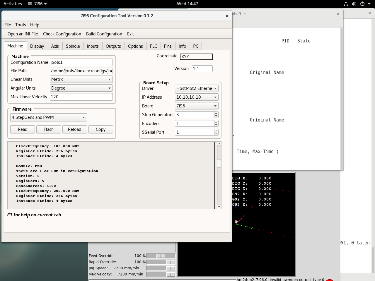
Shows the firmware loaded has PWM, the command in the terminal and linuxcnc running.
PWM is definitely loaded via the 7i96 configuration tool.
Replied by jools on topic 7i96 Can't get PWM output
Shows the firmware loaded has PWM, the command in the terminal and linuxcnc running.
PWM is definitely loaded via the 7i96 configuration tool.
Please Log in or Create an account to join the conversation.
- PCW
-
- Away
- Moderator
-
Less
More
- Posts: 17997
- Thank you received: 5284
20 Nov 2019 15:06 - 20 Nov 2019 15:10 #150763
by PCW
Replied by PCW on topic 7i96 Can't get PWM output
Sorry the command is
halcmd show all *pwmgen*
or
halcmd show all | grep pwm
I forgot that halcmd does not do a simple text match like vanilla grep
but seems to search only for complete tokens
halcmd show all *pwmgen*
or
halcmd show all | grep pwm
I forgot that halcmd does not do a simple text match like vanilla grep
but seems to search only for complete tokens
Last edit: 20 Nov 2019 15:10 by PCW.
Please Log in or Create an account to join the conversation.
- tommylight
-

- Offline
- Moderator
-
Less
More
- Posts: 21767
- Thank you received: 7439
20 Nov 2019 15:10 #150764
by tommylight
Replied by tommylight on topic 7i96 Can't get PWM output
That is a software PWM there, not hardware.
From the beginning:
What firmware do you have on your 7i96, what does readhmi report ?
You will most probably need to flash it with firmware that has hardware PWM, as noted by PCW.
After you flash it, reload and check readhmi again, it has to say PWM somewhere in it's output . Only after this continue setting up the config.
Please Log in or Create an account to join the conversation.
- jools
-
Topic Author
- Offline
- Elite Member
-
Less
More
- Posts: 161
- Thank you received: 15
20 Nov 2019 15:24 #150765
by jools
readhmid produces
This is using an old version of mesaflash hence the segmentation fault but I actually used the 7i96 configuration tool to flash it. When I use the same tool to read it there is no segmentation fault.
Code from 7i96 tool
Jools
Replied by jools on topic 7i96 Can't get PWM output
That is a software PWM there, not hardware.
From the beginning:
What firmware do you have on your 7i96, what does readhmi report ?
You will most probably need to flash it with firmware that has hardware PWM, as noted by PCW.
After you flash it, reload and check readhmi again, it has to say PWM somewhere in it's output . Only after this continue setting up the config.
readhmid produces
jools@jools-1:~$ sudo mesaflash --device 7i96 --addr 10.10.10.10 --readhmid
Configuration Name: HOSTMOT2

General configuration information:

  BoardName : MESA7I96
  FPGA Size: 9 KGates
  FPGA Pins: 144
  Number of IO Ports: 3
  Width of one I/O port: 17
  Clock Low frequency: 100.0000 MHz
  Clock High frequency: 200.0000 MHz
  IDROM Type: 3
  Instance Stride 0: 4
  Instance Stride 1: 64
  Register Stride 0: 256
  Register Stride 1: 256

Modules in configuration:

  Module: DPLL
  There are 1 of DPLL in configuration
  Version: 0
  Registers: 7
  BaseAddress: 7000
  ClockFrequency: 100.000 MHz
  Register Stride: 256 bytes
  Instance Stride: 4 bytes

  Module: WatchDog
  There are 1 of WatchDog in configuration
  Version: 0
  Registers: 3
  BaseAddress: 0C00
  ClockFrequency: 100.000 MHz
  Register Stride: 256 bytes
  Instance Stride: 4 bytes

  Module: IOPort
  There are 3 of IOPort in configuration
  Version: 0
  Registers: 5
  BaseAddress: 1000
  ClockFrequency: 100.000 MHz
  Register Stride: 256 bytes
  Instance Stride: 4 bytes

  Module: PWM
  There are 1 of PWM in configuration
  Version: 0
  Registers: 5
  BaseAddress: 4100
  ClockFrequency: 200.000 MHz
  Register Stride: 256 bytes
  Instance Stride: 4 bytes

  Module: StepGen
  There are 4 of StepGen in configuration
  Version: 2
  Registers: 10
  BaseAddress: 2000
  ClockFrequency: 100.000 MHz
  Register Stride: 256 bytes
  Instance Stride: 4 bytes

  Module: QCount
  There are 1 of QCount in configuration
  Version: 2
  Registers: 5
  BaseAddress: 3000
  ClockFrequency: 100.000 MHz
  Register Stride: 256 bytes
  Instance Stride: 4 bytes

  Module: SSerial
  There are 1 of SSerial in configuration
  Version: 0
  Registers: 6
  BaseAddress: 5B00
  ClockFrequency: 100.000 MHz
  Register Stride: 256 bytes
  Instance Stride: 64 bytes

  Module: Transformer
  There are 1 of Transformer in configuration
  Version: 0
  Registers: 2
  BaseAddress: 7D00
  ClockFrequency: 100.000 MHz
  Register Stride: 256 bytes
  Instance Stride: 4 bytes

  Module: LED
  There are 1 of LED in configuration
  Version: 0
  Registers: 1
  BaseAddress: 0200
  ClockFrequency: 100.000 MHz
  Register Stride: 256 bytes
  Instance Stride: 4 bytes

Configuration pin-out:

IO Connections for P1
Pin#  I/O   Pri. func    Sec. func       Chan      Pin func        Pin Dir

 1      0   IOPort       None
14      1   IOPort       None
 2      2   IOPort       None
15      3   IOPort       None
 3      4   IOPort       None
16      5   IOPort       None
 4      6   IOPort       None
17      7   IOPort       None
 5      8   IOPort       None
 6      9   IOPort       None
 7     10   IOPort       None
 8     11   IOPort       Transformer      0        Drive           (Out)
 9     12   IOPort       Transformer      0        Ref             (Out)
10     13   IOPort       Transformer      0        Null3           (Out)
11     14   IOPort       Transformer      0        Null4           (Out)
12     15   IOPort       Transformer      0        Null5           (Out)
13     16   IOPort       Transformer      0        Null6           (Out)

IO Connections for TB1
Pin#  I/O   Pri. func    Sec. func       Chan      Pin func        Pin Dir

 1     17   IOPort       StepGen          0        Step/Table1     (Out)
14     18   IOPort       StepGen          0        Dir/Table2      (Out)
 2     19   IOPort       StepGen          1        Step/Table1     (Out)
15     20   IOPort       StepGen          1        Dir/Table2      (Out)
 3     21   IOPort       StepGen          2        Step/Table1     (Out)
16     22   IOPort       StepGen          2        Dir/Table2      (Out)
 4     23   IOPort       StepGen          3        Step/Table1     (Out)
17     24   IOPort       StepGen          3        Dir/Table2      (Out)
 5     25   IOPort       PWM              0        PWM             (Out)
 6     26   IOPort       PWM              0        Dir             (Out)
 7     27   IOPort       QCount           0        Quad-A          (In)
 8     28   IOPort       QCount           0        Quad-B          (In)
 9     29   IOPort       QCount           0        Quad-IDX        (In)
10     30   IOPort       SSerial          0        RXData1         (In)
11     31   IOPort       SSerial          0        TXData1         (Out)
12     32   IOPort       SSerial          0        TXEn1           (Out)
Segmentation fault
jools@jools-1:~$
This is using an old version of mesaflash hence the segmentation fault but I actually used the 7i96 configuration tool to flash it. When I use the same tool to read it there is no segmentation fault.
Code from 7i96 tool
Configuration Name: HOSTMOT2

General configuration information:

  BoardName : MESA7I96
  FPGA Size: 9 KGates
  FPGA Pins: 144
  Number of IO Ports: 3
  Width of one I/O port: 17
  Clock Low frequency: 100.0000 MHz
  Clock High frequency: 200.0000 MHz
  IDROM Type: 3
  Instance Stride 0: 4
  Instance Stride 1: 64
  Register Stride 0: 256
  Register Stride 1: 256

Modules in configuration:

  Module: DPLL
  There are 1 of DPLL in configuration
  Version: 0
  Registers: 7
  BaseAddress: 7000
  ClockFrequency: 100.000 MHz
  Register Stride: 256 bytes
  Instance Stride: 4 bytes

  Module: WatchDog
  There are 1 of WatchDog in configuration
  Version: 0
  Registers: 3
  BaseAddress: 0C00
  ClockFrequency: 100.000 MHz
  Register Stride: 256 bytes
  Instance Stride: 4 bytes

  Module: IOPort
  There are 3 of IOPort in configuration
  Version: 0
  Registers: 5
  BaseAddress: 1000
  ClockFrequency: 100.000 MHz
  Register Stride: 256 bytes
  Instance Stride: 4 bytes

  Module: PWM
  There are 1 of PWM in configuration
  Version: 0
  Registers: 5
  BaseAddress: 4100
  ClockFrequency: 200.000 MHz
  Register Stride: 256 bytes
  Instance Stride: 4 bytes

  Module: StepGen
  There are 4 of StepGen in configuration
  Version: 2
  Registers: 10
  BaseAddress: 2000
  ClockFrequency: 100.000 MHz
  Register Stride: 256 bytes
  Instance Stride: 4 bytes

  Module: QCount
  There are 1 of QCount in configuration
  Version: 2
  Registers: 5
  BaseAddress: 3000
  ClockFrequency: 100.000 MHz
  Register Stride: 256 bytes
  Instance Stride: 4 bytes

  Module: SSerial
  There are 1 of SSerial in configuration
  Version: 0
  Registers: 6
  BaseAddress: 5B00
  ClockFrequency: 100.000 MHz
  Register Stride: 256 bytes
  Instance Stride: 64 bytes

  Module: SSR
  There are 1 of SSR in configuration
  Version: 0
  Registers: 2
  BaseAddress: 7D00
  ClockFrequency: 100.000 MHz
  Register Stride: 256 bytes
  Instance Stride: 4 bytes

  Module: LED
  There are 1 of LED in configuration
  Version: 0
  Registers: 1
  BaseAddress: 0200
  ClockFrequency: 100.000 MHz
  Register Stride: 256 bytes
  Instance Stride: 4 bytes

Configuration pin-out:

IO Connections for TB3
Pin#  I/O   Pri. func    Sec. func       Chan      Pin func        Pin Dir

 1      0   IOPort       None
14      1   IOPort       None
 2      2   IOPort       None
15      3   IOPort       None
 3      4   IOPort       None
16      5   IOPort       None
 4      6   IOPort       None
17      7   IOPort       None
 5      8   IOPort       None
 6      9   IOPort       None
 7     10   IOPort       None
 8     11   IOPort       SSR              0        Out-00          (Out)
 9     12   IOPort       SSR              0        Out-01          (Out)
10     13   IOPort       SSR              0        Out-02          (Out)
11     14   IOPort       SSR              0        Out-03          (Out)
12     15   IOPort       SSR              0        Out-04          (Out)
13     16   IOPort       SSR              0        Out-05          (Out)

IO Connections for TB1/TB2
Pin#  I/O   Pri. func    Sec. func       Chan      Pin func        Pin Dir

 1     17   IOPort       StepGen          0        Step/Table1     (Out)
14     18   IOPort       StepGen          0        Dir/Table2      (Out)
 2     19   IOPort       StepGen          1        Step/Table1     (Out)
15     20   IOPort       StepGen          1        Dir/Table2      (Out)
 3     21   IOPort       StepGen          2        Step/Table1     (Out)
16     22   IOPort       StepGen          2        Dir/Table2      (Out)
 4     23   IOPort       StepGen          3        Step/Table1     (Out)
17     24   IOPort       StepGen          3        Dir/Table2      (Out)
 5     25   IOPort       PWM              0        PWM             (Out)
 6     26   IOPort       PWM              0        Dir             (Out)
 7     27   IOPort       QCount           0        Quad-A          (In)
 8     28   IOPort       QCount           0        Quad-B          (In)
 9     29   IOPort       QCount           0        Quad-IDX        (In)
10     30   IOPort       SSerial          0        RXData0         (In)
11     31   IOPort       SSerial          0        TXData0         (Out)
12     32   IOPort       SSerial          0        TXEn0           (Out)
13     33   IOPort       SSR              0        AC Ref          (Out)

IO Connections for P1
Pin#  I/O   Pri. func    Sec. func       Chan      Pin func        Pin Dir

 1     34   IOPort       None
14     35   IOPort       None
 2     36   IOPort       None
15     37   IOPort       None
 3     38   IOPort       None
16     39   IOPort       None
 4     40   IOPort       None
17     41   IOPort       None
 5     42   IOPort       None
 6     43   IOPort       None
 7     44   IOPort       None
 8     45   IOPort       None
 9     46   IOPort       None
10     47   IOPort       None
11     48   IOPort       None
12     49   IOPort       None
13     50   IOPort       None
Jools
Please Log in or Create an account to join the conversation.
- jools
-
Topic Author
- Offline
- Elite Member
-
Less
More
- Posts: 161
- Thank you received: 15
20 Nov 2019 15:28 #150766
by jools
I flashed it via tool then reloaded and then started to set it up in the config tool.
Should this set up a manual PWM or is it a PWM only from the MDI commands?
Replied by jools on topic 7i96 Can't get PWM output
That is a software PWM there, not hardware.
From the beginning:
What firmware do you have on your 7i96, what does readhmi report ?
You will most probably need to flash it with firmware that has hardware PWM, as noted by PCW.
After you flash it, reload and check readhmi again, it has to say PWM somewhere in it's output . Only after this continue setting up the config.
I flashed it via tool then reloaded and then started to set it up in the config tool.
Should this set up a manual PWM or is it a PWM only from the MDI commands?
Please Log in or Create an account to join the conversation.
- tommylight
-
- Offline
- Moderator
-
Less
More
- Posts: 21767
- Thank you received: 7439
20 Nov 2019 15:45 #150769
by tommylight
Replied by tommylight on topic 7i96 Can't get PWM output
Add the num_pwm = 1 to loadrt line for Mesa 7i76, or see if there is a provision for setting that in tool.
If not, after adding pwm to loadrt, there are some more lines to add to hal file that i do not know for sure, like scale, frequency and some other stuff that again i think PCW mentioned somewhere. There are 3 topics with this same problem so hard to keep track.
Another way of making this work is to create a config for 5i25 with hardware pwm and copy/paste the hal entries to your config, and just change the 5i25 to 7i96 in those lines.
Please Log in or Create an account to join the conversation.
Time to create page: 0.138 seconds