Mesa 7i96 with paralel BOB
- ikkuh
-
 Topic Author
- Offline
- Elite Member
-

- Posts: 272
- Thank you received: 47
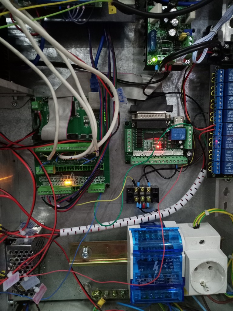
I use an 7i96 with a Chinese paralel BOB on connector 3. I use some special firmware so that I can use the BOB for a pwm signal for my spindle. This all works great.
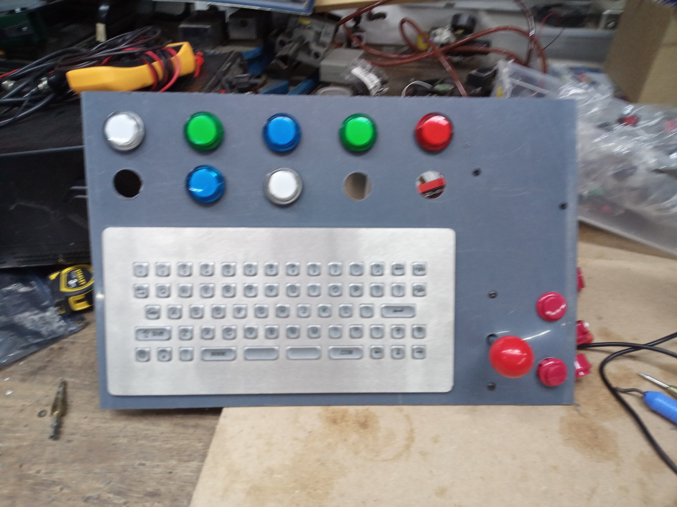
Lately I added a lot of switches through a Chinese USB Arcade controller. That controller takes care of all the inputs and using some of Ask Jerry's video I got it all working.
But now I try to use the not used in and outputs of the BOB, but I just can not seem to make it work. The inputs show up in a halcmd show pins, but I just can not make an output working. How do I control one of the outputs on the BOB in my hal file?
29 bit OUT FALSE hm2_7i96.0.gpio.000.in ==> home-joint-0
29 bit OUT TRUE hm2_7i96.0.gpio.000.in_not
29 bit IN FALSE hm2_7i96.0.gpio.000.out
29 bit OUT FALSE hm2_7i96.0.gpio.001.in ==> home-joint-1
29 bit OUT TRUE hm2_7i96.0.gpio.001.in_not
29 bit IN FALSE hm2_7i96.0.gpio.001.out
29 bit OUT FALSE hm2_7i96.0.gpio.002.in ==> home-joint-2
29 bit OUT TRUE hm2_7i96.0.gpio.002.in_not
29 bit IN FALSE hm2_7i96.0.gpio.002.out
29 bit OUT FALSE hm2_7i96.0.gpio.003.in ==> home-joint-3
29 bit OUT TRUE hm2_7i96.0.gpio.003.in_not
29 bit IN FALSE hm2_7i96.0.gpio.003.out
29 bit OUT FALSE hm2_7i96.0.gpio.004.in
29 bit OUT TRUE hm2_7i96.0.gpio.004.in_not
29 bit IN FALSE hm2_7i96.0.gpio.004.out
29 bit OUT FALSE hm2_7i96.0.gpio.005.in
29 bit OUT TRUE hm2_7i96.0.gpio.005.in_not
29 bit IN FALSE hm2_7i96.0.gpio.005.out
29 bit OUT FALSE hm2_7i96.0.gpio.006.in
29 bit OUT TRUE hm2_7i96.0.gpio.006.in_not
29 bit IN FALSE hm2_7i96.0.gpio.006.out
29 bit OUT FALSE hm2_7i96.0.gpio.007.in
29 bit OUT TRUE hm2_7i96.0.gpio.007.in_not
29 bit IN FALSE hm2_7i96.0.gpio.007.out
29 bit OUT FALSE hm2_7i96.0.gpio.008.in
29 bit OUT TRUE hm2_7i96.0.gpio.008.in_not
29 bit IN FALSE hm2_7i96.0.gpio.008.out
29 bit OUT TRUE hm2_7i96.0.gpio.009.in
29 bit OUT FALSE hm2_7i96.0.gpio.009.in_not ==> probe-input
29 bit IN FALSE hm2_7i96.0.gpio.009.out
29 bit OUT TRUE hm2_7i96.0.gpio.010.in
29 bit OUT FALSE hm2_7i96.0.gpio.010.in_not ==> remote-estop
29 bit IN FALSE hm2_7i96.0.gpio.010.out
29 bit OUT FALSE hm2_7i96.0.gpio.011.in
29 bit OUT TRUE hm2_7i96.0.gpio.011.in_not
29 bit OUT FALSE hm2_7i96.0.gpio.012.in
29 bit OUT TRUE hm2_7i96.0.gpio.012.in_not
29 bit OUT FALSE hm2_7i96.0.gpio.013.in
29 bit OUT TRUE hm2_7i96.0.gpio.013.in_not
29 bit OUT FALSE hm2_7i96.0.gpio.014.in
29 bit OUT TRUE hm2_7i96.0.gpio.014.in_not
29 bit OUT FALSE hm2_7i96.0.gpio.015.in
29 bit OUT TRUE hm2_7i96.0.gpio.015.in_not
29 bit OUT FALSE hm2_7i96.0.gpio.016.in
29 bit OUT TRUE hm2_7i96.0.gpio.016.in_not
29 bit OUT FALSE hm2_7i96.0.gpio.017.in
29 bit OUT TRUE hm2_7i96.0.gpio.017.in_not
29 bit OUT FALSE hm2_7i96.0.gpio.018.in
29 bit OUT TRUE hm2_7i96.0.gpio.018.in_not
29 bit OUT FALSE hm2_7i96.0.gpio.019.in
29 bit OUT TRUE hm2_7i96.0.gpio.019.in_not
29 bit OUT FALSE hm2_7i96.0.gpio.020.in
29 bit OUT TRUE hm2_7i96.0.gpio.020.in_not
29 bit OUT FALSE hm2_7i96.0.gpio.021.in
29 bit OUT TRUE hm2_7i96.0.gpio.021.in_not
29 bit OUT FALSE hm2_7i96.0.gpio.022.in
29 bit OUT TRUE hm2_7i96.0.gpio.022.in_not
29 bit OUT FALSE hm2_7i96.0.gpio.023.in
29 bit OUT TRUE hm2_7i96.0.gpio.023.in_not
29 bit OUT FALSE hm2_7i96.0.gpio.024.in
29 bit OUT TRUE hm2_7i96.0.gpio.024.in_not
29 bit OUT FALSE hm2_7i96.0.gpio.025.in
29 bit OUT TRUE hm2_7i96.0.gpio.025.in_not
29 bit OUT FALSE hm2_7i96.0.gpio.026.in
29 bit OUT TRUE hm2_7i96.0.gpio.026.in_not
29 bit OUT FALSE hm2_7i96.0.gpio.027.in
29 bit OUT TRUE hm2_7i96.0.gpio.027.in_not
29 bit OUT FALSE hm2_7i96.0.gpio.028.in
29 bit OUT TRUE hm2_7i96.0.gpio.028.in_not
29 bit OUT FALSE hm2_7i96.0.gpio.029.in
29 bit OUT TRUE hm2_7i96.0.gpio.029.in_not
29 bit OUT TRUE hm2_7i96.0.gpio.030.in
29 bit OUT FALSE hm2_7i96.0.gpio.030.in_not
29 bit IN TRUE hm2_7i96.0.gpio.030.out
29 bit OUT FALSE hm2_7i96.0.gpio.031.in
29 bit OUT TRUE hm2_7i96.0.gpio.031.in_not
29 bit IN TRUE hm2_7i96.0.gpio.031.out
29 bit OUT FALSE hm2_7i96.0.gpio.032.in
29 bit OUT TRUE hm2_7i96.0.gpio.032.in_not
29 bit IN FALSE hm2_7i96.0.gpio.032.out
29 bit OUT FALSE hm2_7i96.0.gpio.033.in
29 bit OUT TRUE hm2_7i96.0.gpio.033.in_not
29 bit OUT FALSE hm2_7i96.0.gpio.034.in
29 bit OUT TRUE hm2_7i96.0.gpio.034.in_not
29 bit OUT TRUE hm2_7i96.0.gpio.035.in
29 bit OUT FALSE hm2_7i96.0.gpio.035.in_not
29 bit IN FALSE hm2_7i96.0.gpio.035.out
29 bit OUT FALSE hm2_7i96.0.gpio.036.in
29 bit OUT TRUE hm2_7i96.0.gpio.036.in_not
29 bit OUT TRUE hm2_7i96.0.gpio.037.in
29 bit OUT FALSE hm2_7i96.0.gpio.037.in_not
29 bit IN FALSE hm2_7i96.0.gpio.037.out
29 bit OUT FALSE hm2_7i96.0.gpio.038.in
29 bit OUT TRUE hm2_7i96.0.gpio.038.in_not
29 bit OUT TRUE hm2_7i96.0.gpio.039.in
29 bit OUT FALSE hm2_7i96.0.gpio.039.in_not
29 bit IN FALSE hm2_7i96.0.gpio.039.out
29 bit OUT FALSE hm2_7i96.0.gpio.040.in
29 bit OUT TRUE hm2_7i96.0.gpio.040.in_not
29 bit OUT TRUE hm2_7i96.0.gpio.041.in
29 bit OUT FALSE hm2_7i96.0.gpio.041.in_not
29 bit IN FALSE hm2_7i96.0.gpio.041.out
29 bit OUT FALSE hm2_7i96.0.gpio.042.in
29 bit OUT TRUE hm2_7i96.0.gpio.042.in_not
29 bit OUT FALSE hm2_7i96.0.gpio.043.in
29 bit OUT TRUE hm2_7i96.0.gpio.043.in_not
29 bit OUT FALSE hm2_7i96.0.gpio.044.in
29 bit OUT TRUE hm2_7i96.0.gpio.044.in_not
29 bit OUT TRUE hm2_7i96.0.gpio.045.in
29 bit OUT FALSE hm2_7i96.0.gpio.045.in_not
29 bit IN FALSE hm2_7i96.0.gpio.045.out
29 bit OUT TRUE hm2_7i96.0.gpio.046.in
29 bit OUT FALSE hm2_7i96.0.gpio.046.in_not
29 bit IN FALSE hm2_7i96.0.gpio.046.out
29 bit OUT TRUE hm2_7i96.0.gpio.047.in
29 bit OUT FALSE hm2_7i96.0.gpio.047.in_not
29 bit IN FALSE hm2_7i96.0.gpio.047.out
29 bit OUT TRUE hm2_7i96.0.gpio.048.in
29 bit OUT FALSE hm2_7i96.0.gpio.048.in_not
29 bit IN FALSE hm2_7i96.0.gpio.048.out
29 bit OUT TRUE hm2_7i96.0.gpio.049.in
29 bit OUT FALSE hm2_7i96.0.gpio.049.in_not
29 bit IN FALSE hm2_7i96.0.gpio.049.out
29 bit OUT TRUE hm2_7i96.0.gpio.050.in
29 bit OUT FALSE hm2_7i96.0.gpio.050.in_not
29 bit IN FALSE hm2_7i96.0.gpio.050.out
My guess is that
is the first output on the BOB. But I might be wrong.29 bit IN TRUE hm2_7i96.0.gpio.030.out
Is there anybody who could me out? I am not a wizard myself, and sure could use some help with this.
Attachments:
Please Log in or Create an account to join the conversation.
- tommylight
-

- Away
- Moderator
-

- Posts: 21169
- Thank you received: 7231
Attachments:
Please Log in or Create an account to join the conversation.
- ikkuh
-
 Topic Author
- Offline
- Elite Member
-

- Posts: 272
- Thank you received: 47
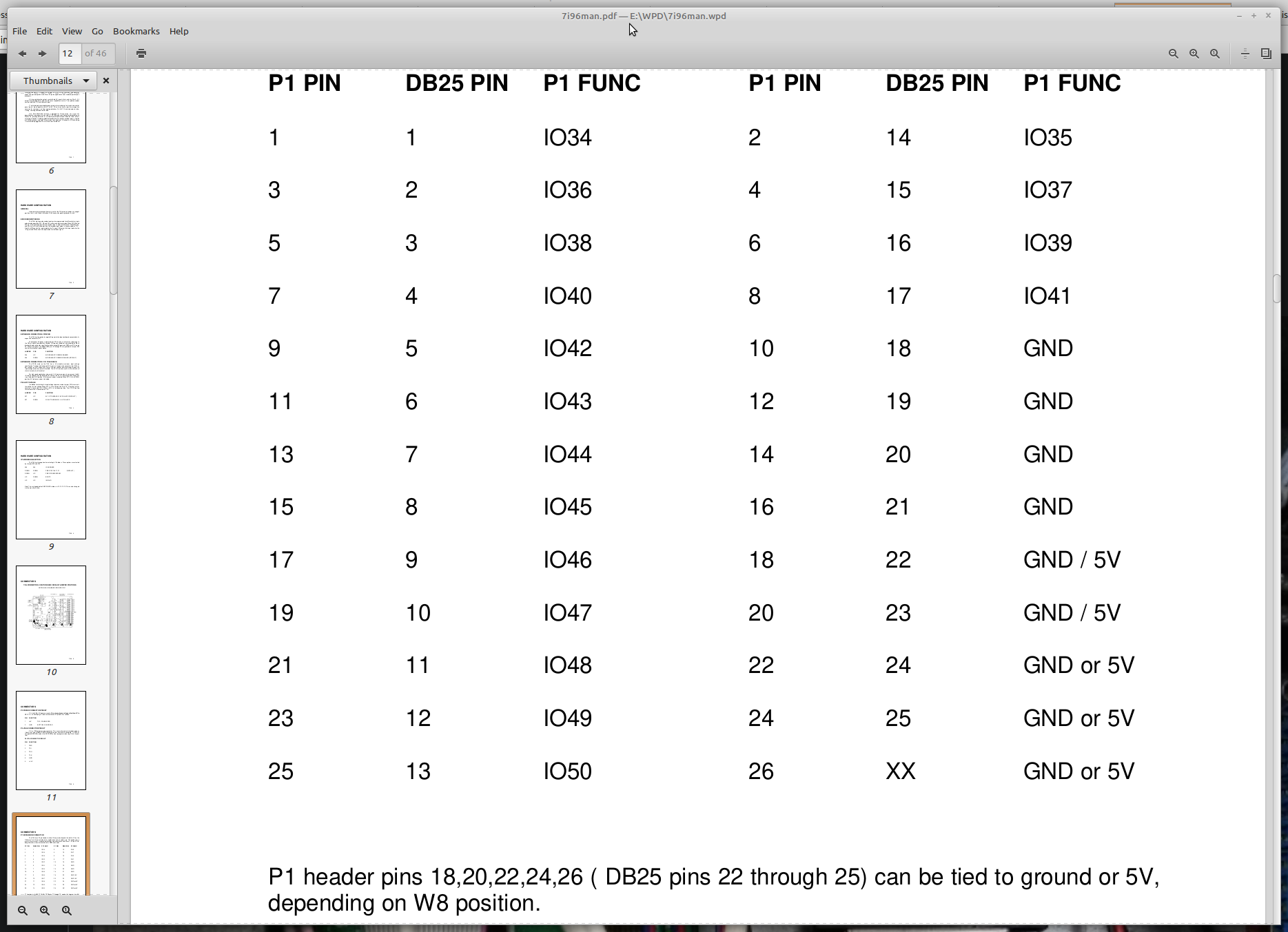
IO 34 is the first on the header as can be seen from the 7i96 manual:
As I said I am no wizard and need help.
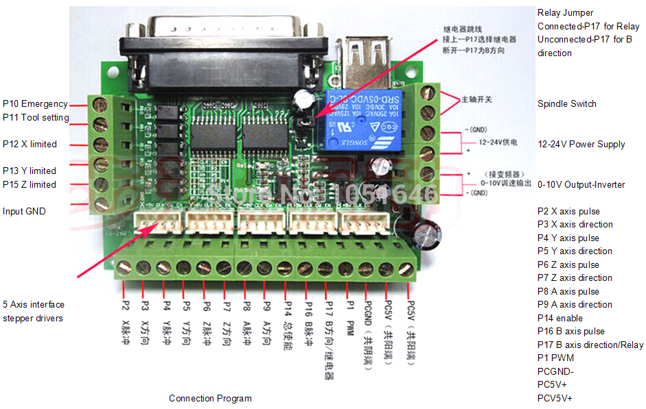
What do I need to do to get the P2 pin (see image) high so I can attach an Led or other load to it? Most Led's will be signaling a gmoccapy/halui state. So the outputs on screen need to be coupled to the Led's controlled by the Bob gpio pins.
According to the 7i96 they indeed start at gpio.034. (Why does the range of output pins start at 030, where are the 4 missing outputs?)
If you could please make a simple example for the mist control maybe? So when I connect the Mist-on in postgui.hal to a button on the joystick card I would like to be able to see the state change through a Led in the button controlled by the Bob.
net Mist-on <= halui.mist.on <= input.0.btn-pinkie
(My git repo can be found at: git.cnckloon.nl/CNCZone/mesa_2019 )
This works and the pictogram on screen changes. Now I need to figure out how to connect the internal state of the Mist component to an output so I can light up an Led.
Attachments:
Please Log in or Create an account to join the conversation.
- tommylight
-

- Away
- Moderator
-

- Posts: 21169
- Thank you received: 7231
Please Log in or Create an account to join the conversation.
- ikkuh
-
 Topic Author
- Offline
- Elite Member
-

- Posts: 272
- Thank you received: 47
Please Log in or Create an account to join the conversation.
- PCW
-

- Offline
- Moderator
-

- Posts: 17594
- Thank you received: 5145
net Mist-on <= halui.mist.on <= input.0.btn-pinkie => hm2_7i96.0.gpio.036.out # DB25 pin 2
Note that neither statement will work unless you disable the stepgen on DB25 pin 2
by setting num_stepgens=5 in your hal or ini file (since DB25 pin 2 is the sixth stepgen)
Please Log in or Create an account to join the conversation.
- ikkuh
-
 Topic Author
- Offline
- Elite Member
-

- Posts: 272
- Thank you received: 47
setp hm2_7i96.0.gpio.036.is_output true
net Mist-on <= halui.mist.on <= input.0.btn-pinkie => hm2_7i96.0.gpio.036.out # DB25 pin 2
Note that neither statement will work unless you disable the stepgen on DB25 pin 2
by setting num_stepgens=5 in your hal or ini file (since DB25 pin 2 is the sixth stepgen)
Thanks! I will try right away!
Please Log in or Create an account to join the conversation.
- ikkuh
-
 Topic Author
- Offline
- Elite Member
-

- Posts: 272
- Thank you received: 47
setp hm2_7i96.0.gpio.036.is_output true
net Mist-on <= halui.mist.on <= input.0.btn-pinkie => hm2_7i96.0.gpio.036.out # DB25 pin 2
Note that neither statement will work unless you disable the stepgen on DB25 pin 2
by setting num_stepgens=5 in your hal or ini file (since DB25 pin 2 is the sixth stepgen)
Nope, I do not get it to work.
I mentioned I use the special firmware for the 7i96 where the pwm signals are available on the PWM pins, maybe that's the problem?
When I start LinuxCNC
LINUXCNC - 2.9.0-pre0-3195-g57f06b625I did change the num_stepgens:
loadrt [HOSTMOT2](DRIVER) board_ip=[HOSTMOT2](IPADDRESS) config="num_encoders=[HOSTMOT2](ENCODERS)num_stepgens=5"sserial_port_0=[HOSTMOT2](SSERIAL_PORT)
setp hm2_[HOSTMOT2](BOARD).0.watchdog.timeout_ns 25000000
hm2: loading Mesa HostMot2 driver version 0.15
hm2_eth: loading Mesa AnyIO HostMot2 ethernet driver version 0.2
hm2_eth: 10.10.10.10: INFO: Hardware address (MAC): 00:60:1b:16:00:35
hm2_eth: discovered 7I96
hm2/hm2_7i96.0: Low Level init 0.15
hm2/hm2_7i96.0: Smart Serial Firmware Version 43
hm2/hm2_7i96.0: 51 I/O Pins used:
hm2/hm2_7i96.0: IO Pin 000 (TB3-01): IOPort
hm2/hm2_7i96.0: IO Pin 001 (TB3-02): IOPort
hm2/hm2_7i96.0: IO Pin 002 (TB3-03): IOPort
hm2/hm2_7i96.0: IO Pin 003 (TB3-04): IOPort
hm2/hm2_7i96.0: IO Pin 004 (TB3-05): IOPort
hm2/hm2_7i96.0: IO Pin 005 (TB3-06): IOPort
hm2/hm2_7i96.0: IO Pin 006 (TB3-07): IOPort
hm2/hm2_7i96.0: IO Pin 007 (TB3-08): IOPort
hm2/hm2_7i96.0: IO Pin 008 (TB3-09): IOPort
hm2/hm2_7i96.0: IO Pin 009 (TB3-10): IOPort
hm2/hm2_7i96.0: IO Pin 010 (TB3-11): IOPort
hm2/hm2_7i96.0: IO Pin 011 (TB3-13/TB3-14): SSR #0, pin Out-00 (Output)
hm2/hm2_7i96.0: IO Pin 012 (TB3-15/TB3-16): SSR #0, pin Out-01 (Output)
hm2/hm2_7i96.0: IO Pin 013 (TB3-17/TB3-18): SSR #0, pin Out-02 (Output)
hm2/hm2_7i96.0: IO Pin 014 (TB3-19/TB3-20): SSR #0, pin Out-03 (Output)
hm2/hm2_7i96.0: IO Pin 015 (TB3-21/TB3-22): SSR #0, pin Out-04 (Output)
hm2/hm2_7i96.0: IO Pin 016 (TB3-23/TB3-24): SSR #0, pin Out-05 (Output)
hm2/hm2_7i96.0: IO Pin 017 (TB1-02/TB1-03): StepGen #0, pin Step (Output)
hm2/hm2_7i96.0: IO Pin 018 (TB1-04/TB1-05): StepGen #0, pin Direction (Output)
hm2/hm2_7i96.0: IO Pin 019 (TB1-08/TB1-09): StepGen #1, pin Step (Output)
hm2/hm2_7i96.0: IO Pin 020 (TB1-10/TB1-11): StepGen #1, pin Direction (Output)
hm2/hm2_7i96.0: IO Pin 021 (TB1-14/TB1-15): StepGen #2, pin Step (Output)
hm2/hm2_7i96.0: IO Pin 022 (TB1-16/TB1-17): StepGen #2, pin Direction (Output)
hm2/hm2_7i96.0: IO Pin 023 (TB1-20/TB1-21): StepGen #3, pin Step (Output)
hm2/hm2_7i96.0: IO Pin 024 (TB1-22-TB1-23): StepGen #3, pin Direction (Output)
hm2/hm2_7i96.0: IO Pin 025 (TB2-02/TB2-03): StepGen #4, pin Step (Output)
hm2/hm2_7i96.0: IO Pin 026 (TB2-04/TB2-05): StepGen #4, pin Direction (Output)
hm2/hm2_7i96.0: IO Pin 027 (TB2-07/TB2-08): Encoder #0, pin A (Input)
hm2/hm2_7i96.0: IO Pin 028 (TB2-10/TB2-11): Encoder #0, pin B (Input)
hm2/hm2_7i96.0: IO Pin 029 (TB2-13/TB2-14): Encoder #0, pin Index (Input)
hm2/hm2_7i96.0: IO Pin 030 (TB2-16/TB2-17): IOPort
hm2/hm2_7i96.0: IO Pin 031 (TB2-18/TB2-19): IOPort
hm2/hm2_7i96.0: IO Pin 032 (internal): IOPort
hm2/hm2_7i96.0: IO Pin 033 (internal): SSR #0, pin AC Ref (internal) (Output)
hm2/hm2_7i96.0: IO Pin 034 (P1-01): PWMGen #0, pin Out0 (PWM or Up) (Output)
hm2/hm2_7i96.0: IO Pin 035 (P1-02): IOPort
hm2/hm2_7i96.0: IO Pin 036 (P1-03): StepGen #5, pin Step (Output)
hm2/hm2_7i96.0: IO Pin 037 (P1-04): IOPort
hm2/hm2_7i96.0: IO Pin 038 (P1-05): StepGen #5, pin Direction (Output)
hm2/hm2_7i96.0: IO Pin 039 (P1-06): IOPort
hm2/hm2_7i96.0: IO Pin 040 (P1-07): StepGen #6, pin Step (Output)
hm2/hm2_7i96.0: IO Pin 041 (P1-08): IOPort
hm2/hm2_7i96.0: IO Pin 042 (P1-09): StepGen #6, pin Direction (Output)
hm2/hm2_7i96.0: IO Pin 043 (P1-11): StepGen #7, pin Step (Output)
hm2/hm2_7i96.0: IO Pin 044 (P1-13): StepGen #7, pin Direction (Output)
hm2/hm2_7i96.0: IO Pin 045 (P1-15): IOPort
hm2/hm2_7i96.0: IO Pin 046 (P1-17): IOPort
hm2/hm2_7i96.0: IO Pin 047 (P1-19): IOPort
hm2/hm2_7i96.0: IO Pin 048 (P1-21): IOPort
hm2/hm2_7i96.0: IO Pin 049 (P1-23): IOPort
hm2/hm2_7i96.0: IO Pin 050 (P1-25): IOPort
hm2/hm2_7i96.0: registered
hm2_eth: in hm2_eth_reset
hm2_eth: HostMot2 ethernet driver unloaded
hm2: unloadingThe Enable, B-Axis pins on the BOB are all high.
The X axis,Y axis, Z axis and A axis pins on the BOB are all low.
Please Log in or Create an account to join the conversation.
- PCW
-

- Offline
- Moderator
-

- Posts: 17594
- Thank you received: 5145
mesaflash --device 7i96 --addr 10.10.10.10 --readhmid
report
Edit looking at LinuxCNCs startup, I think something is wrong on the driver command
line, maybe quote or space related, since all stepgens seem to have been enabled.
Having all stepgens enabled means the the num_stepgens=5 was not parsed
correctly so there is a syntax error on the command line.
Please Log in or Create an account to join the conversation.
- ikkuh
-
 Topic Author
- Offline
- Elite Member
-

- Posts: 272
- Thank you received: 47
What does
mesaflash --device 7i96 --addr 10.10.10.10 --readhmid
report
I will be in the workshop in a few hours, will post the report.
Edit looking at LinuxCNCs startup, I think something is wrong on the driver command
line, maybe quote or space related, since all stepgens seem to have been enabled.
Having all stepgens enabled means the the num_stepgens=5 was not parsed
correctly so there is a syntax error on the command line.
I noticed that too, but when leaving out the spaces surrounding the num_stepgens LinuxCNC would not start. I will look into that when I am in the workshop. Thanks for noticing that, it looked odd to me too.
Please Log in or Create an account to join the conversation.


