YASKAWA SERVOPACK Speed-Control instead Postion Control
- Becksvill
- Offline
- Elite Member
-

Less
More
- Posts: 192
- Thank you received: 88
02 Feb 2022 19:57 #233827
by Becksvill
Replied by Becksvill on topic YASKAWA SERVOPACK Speed-Control instead Postion Control
Hey I have done several yaskawa servo retrofits to Linuxcnc
I found I had to use torque control to get good enough accuracy and power
I'll try check back here later to see any replies as I can probably save you some time
I found I had to use torque control to get good enough accuracy and power
I'll try check back here later to see any replies as I can probably save you some time
Please Log in or Create an account to join the conversation.
- nighteagle
- Offline
- Senior Member
-

Less
More
- Posts: 72
- Thank you received: 6
03 Feb 2022 06:50 #233859
by nighteagle
Replied by nighteagle on topic YASKAWA SERVOPACK Speed-Control instead Postion Control
Hello Becksvill,
you are welcome - i'm waiting for my mesa-card then i think i have so many questions
But for now i will first take the connection.
Have you some special informations for the connection of the yaskawas to mesa cards and configure in linuxcnc?
Regards,
Philipp
you are welcome - i'm waiting for my mesa-card then i think i have so many questions
But for now i will first take the connection.
Have you some special informations for the connection of the yaskawas to mesa cards and configure in linuxcnc?
Regards,
Philipp
Please Log in or Create an account to join the conversation.
- nighteagle
- Offline
- Senior Member
-

Less
More
- Posts: 72
- Thank you received: 6
09 Feb 2022 10:55 #234383
by nighteagle
Replied by nighteagle on topic YASKAWA SERVOPACK Speed-Control instead Postion Control
Hello ehb,
so these days my mesa-card arrived.
I study your datasheet and compare with mine on page 35 of yours you see the output Signals of CN1:
PHA 4 (1)
PHB 37 (2)
PHC 21 (3)
AL01 25 (1)
AL02 40 (2)
AL03 42 (3)
On my Datasheet is some different on Page 25:
PHA 42 (1)
PHB 40 (2)
PHC 25 (3)
AL01 4 (1)
AL02 21 (2)
AL03 37 (3)
So is this a Typo-Mistake of the Sheets? But your sheet is not for special type is more a general-datasheet?
My datasheet is special for the CACR-SR__AC and AE types.
I have a Yaskawa CACR-SR03AC1ER
Please Log in or Create an account to join the conversation.
- nighteagle
- Offline
- Senior Member
-

Less
More
- Posts: 72
- Thank you received: 6
12 Feb 2022 18:10 - 13 Feb 2022 18:42 #234653
by nighteagle
Replied by nighteagle on topic YASKAWA SERVOPACK Speed-Control instead Postion Control
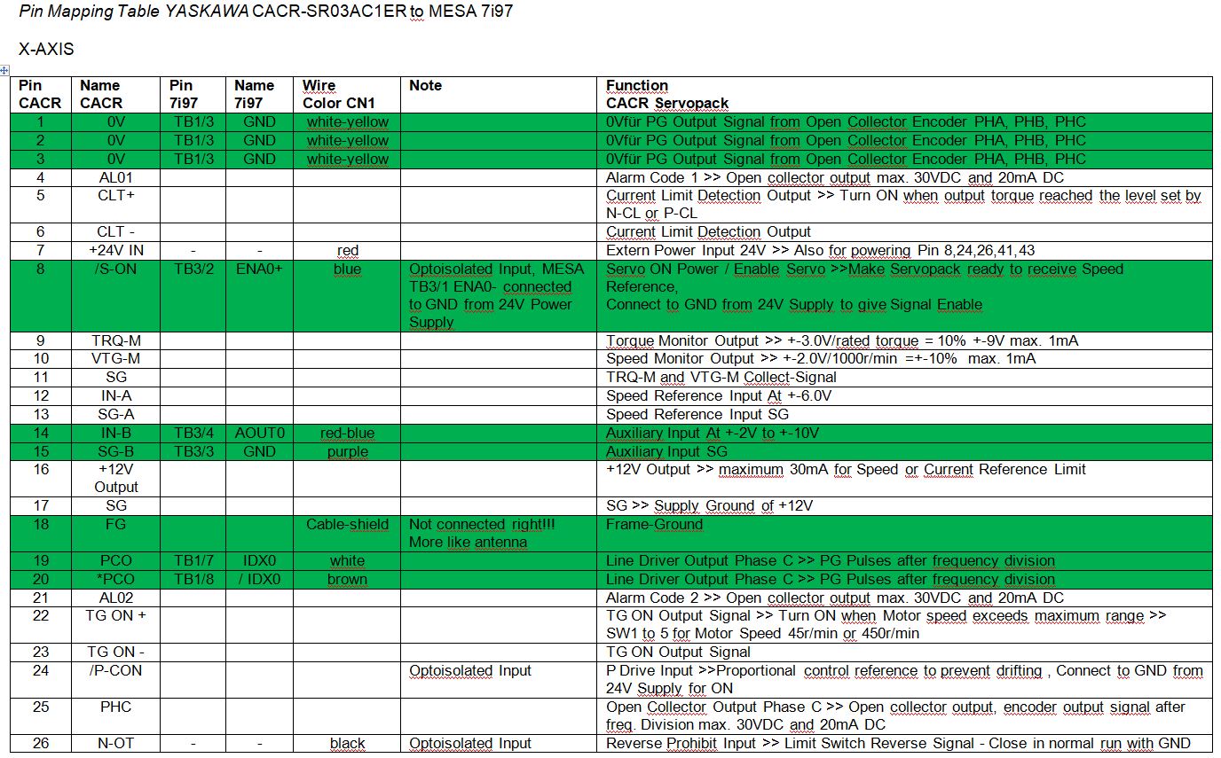
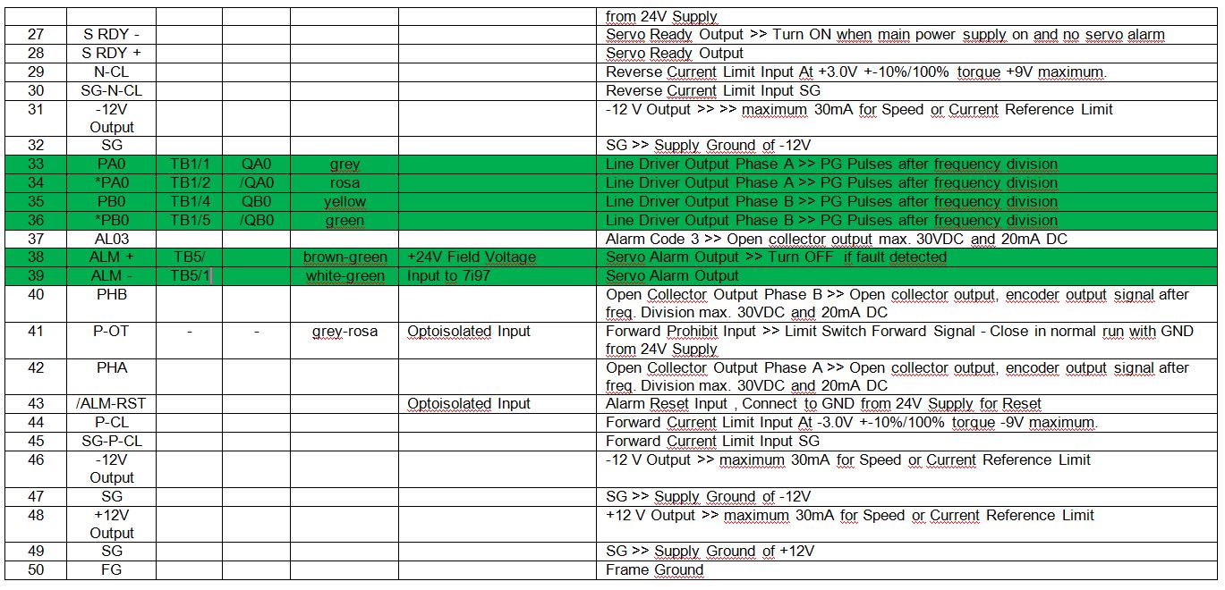
Hello,so here i have my first idea for connection - the fields with the green-color are the connection my machine have before i made the retrofit - here i see not all the others is connected to the Yaskawas.. so no need for most of them.
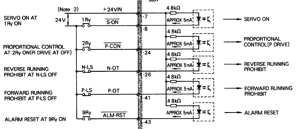
The N-OT and P-OT are limit-switches on the machine and here directly connected to the CN2 connector of the Yaskawa Servopack
Then the +24V voltage for the optocoupler is connected to the Yaskawa Servopack on Pin 7. That is all.
The N-OT and P-OT are limit-switches on the machine and here directly connected to the CN2 connector of the Yaskawa Servopack
Then the +24V voltage for the optocoupler is connected to the Yaskawa Servopack on Pin 7. That is all.
Attachments:
Last edit: 13 Feb 2022 18:42 by nighteagle. Reason: New Connection-Mapping
Please Log in or Create an account to join the conversation.
- nighteagle
- Offline
- Senior Member
-

Less
More
- Posts: 72
- Thank you received: 6
13 Feb 2022 18:45 - 13 Feb 2022 18:49 #234717
by nighteagle
Replied by nighteagle on topic YASKAWA SERVOPACK Speed-Control instead Postion Control
- Pin 7: 24 V
- 8: Enable signal, needs to be connected to ground to enable (on my machine another relay is switched, called "K125")
- 26 & 41, beyond limit switch (drives will show "Pot" on the display if I remember correctly, for positive over travel.
- 43: Drive reset (? not sure when this is used)
- 28: 24 V
- 27: Output from drive to say "Axis OK, drive ready"
- 9 & 10: No idea really
- 11: 0V
- 15: GND for +-10V input
- 14: +-10 V
- 18: Wire shield
- 19, 20, 33, 34, 35, 36 are encoder outputs from drive to Mesa
@ehb
Pin 9&10 are Monitoring - you don't need connect.
Have a look on my connection-table the green ones are the only ones i need
And the extra relay - you don't need it - you can connect to the optocoupler of the yaskawa servopack.
Attachments:
Last edit: 13 Feb 2022 18:49 by nighteagle.
Please Log in or Create an account to join the conversation.
- nighteagle
- Offline
- Senior Member
-

Less
More
- Posts: 72
- Thank you received: 6
02 Mar 2022 14:17 #236177
by nighteagle
Replied by nighteagle on topic YASKAWA SERVOPACK Speed-Control instead Postion Control
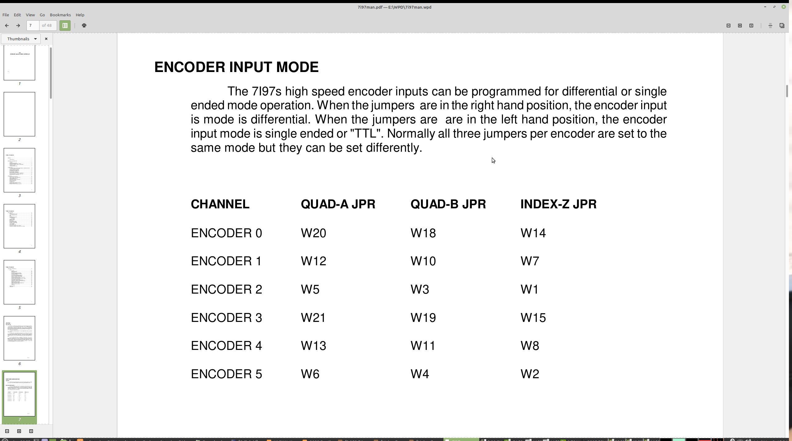
Have someone an iformation how to set the jumper of 7i97 for the encoder to use Differential mode? The Datasheet have no info about this and the mesa-website have problems for downloading pdf from other cards like a 7i77. So missing informations about the function of the 7i97 is very frustaing...
Please Log in or Create an account to join the conversation.
- tommylight
-

- Away
- Moderator
-

Less
More
- Posts: 20531
- Thank you received: 6988
02 Mar 2022 14:26 #236178
by tommylight
Replied by tommylight on topic YASKAWA SERVOPACK Speed-Control instead Postion Control
Attachments:
Please Log in or Create an account to join the conversation.
- nighteagle
- Offline
- Senior Member
-

Less
More
- Posts: 72
- Thank you received: 6
02 Mar 2022 14:30 #236179
by nighteagle
Replied by nighteagle on topic YASKAWA SERVOPACK Speed-Control instead Postion Control
Hello,
no - on page 7 of the manual i have the P1 Connectors of the 7i97. And also your image show not the Jumper on the Board - so which position is what?
no - on page 7 of the manual i have the P1 Connectors of the 7i97. And also your image show not the Jumper on the Board - so which position is what?
Please Log in or Create an account to join the conversation.
- tommylight
-

- Away
- Moderator
-

Less
More
- Posts: 20531
- Thank you received: 6988
02 Mar 2022 14:43 #236185
by tommylight
Replied by tommylight on topic YASKAWA SERVOPACK Speed-Control instead Postion Control
Attachments:
Please Log in or Create an account to join the conversation.
- nighteagle
- Offline
- Senior Member
-

Less
More
- Posts: 72
- Thank you received: 6
02 Mar 2022 15:59 #236195
by nighteagle
Replied by nighteagle on topic YASKAWA SERVOPACK Speed-Control instead Postion Control
Okay - it looks like you don't understand me.
Is there a logcial table or something like this?
Like:
Jumper Connected Function
W2 1-2 something
W2 2-3 something
Because what means right Hand position in the text? Right Hand from what position? That is all trash information and not usable... i have found some mistakes also and here i will be absolutely sure to set correct.
And if you look at the image - can you read something of the numbers?
On the image from the manual - looks like Default-Config of the Jumper - but who knows?
And what this Default of the image mean? TTL or Differential?
Please Log in or Create an account to join the conversation.
Time to create page: 0.156 seconds


