fixing a mess i made, probably...
- ississ
-

- Offline
- Senior Member
-

Less
More
- Posts: 68
- Thank you received: 25
24 May 2024 07:43 #301294
by ississ
Replied by ississ on topic fixing a mess i made, probably...
"(In the arduino code, I saw analog write function used to write to the pin and got confused with the whole analog pwm thing)"
Simple google with "arduino analogwrite" should help (link to arduino function reference).
Original arduino boards using small avr cpus do not have analog output. So they decided to name the pwm output function analogwrite() and use the resistor-capacitor filter to get analog output from pwm. Resistor and capacitor are not on the arduino board.
Using analogwrite() in arduino code would output pwm square wave which is just what is needed.
I think that the transistor markings are wrong, BC547 is npn so normally E should be connected to ground and C to drive pwm input.
"How is the transistor inverting the signal from active high to active low in this circuit? "
If B & E are swapped in the image, high voltage on base will connect C & B -> transisto pulls sv pin low -> signal from arduino is inverted.
Without proper documentation it's very hard to guess how to connect the drive. One possibility is to open it and try to figure out how the input side is done. I don't recommend that if you are not familiar with that kind of work with electronics.
Some drives does not like 100% pwm. Also check that the switches are set correctly.
Please Log in or Create an account to join the conversation.
- Aciera
-

- Offline
- Administrator
-

Less
More
- Posts: 4709
- Thank you received: 2106
24 May 2024 07:50 - 24 May 2024 07:53 #301296
by Aciera
Replied by Aciera on topic fixing a mess i made, probably...
Connecting GND to the Collector and (presumably) SV to the Emitter this doesn't make much sense to me.
If I wanted to invert the PWM signal (presuming that SV is pulled up when open) then I would connect SV by resistor to the Collector and connect the Emitter to GND.
[edit]
So I'd say the 'C' and 'E' markings are wrong as suggested in the previous post.
If I wanted to invert the PWM signal (presuming that SV is pulled up when open) then I would connect SV by resistor to the Collector and connect the Emitter to GND.
[edit]
So I'd say the 'C' and 'E' markings are wrong as suggested in the previous post.
Last edit: 24 May 2024 07:53 by Aciera.
Please Log in or Create an account to join the conversation.
- pmchetan
- Offline
- Senior Member
-
Less
More
- Posts: 58
- Thank you received: 3
24 May 2024 10:36 - 24 May 2024 10:48 #301302
by pmchetan
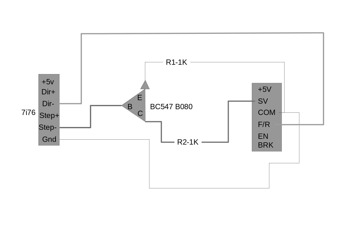
The way I understand it the classic transistor operation like a switch:
The logic high from the pwm signal from 7i76 means current flows through the base terminal, which means the transistor is in forward bias, and the current will be allowed to flow through collector to emitter. When the pwm signal is low, transistor is in reverse bias and some current flows through base terminal to the emitter and the path between collector and the emitter is blocked.
So if thats how it works, there will be a small current flowing from the base terminal to emitter whenever the PWM signal supplies logic low and since emitter is connected to ground of the drive, that current does nothing and when the PWM signal supplies logic high, there's no current since it just connects the collector to the emitter which are in turn attached to sv and common on the drive.
What am I missing? how is the pwm signals reaching the drive pins?
Replied by pmchetan on topic fixing a mess i made, probably...
- The base terminal of the transistor is getting the pwm signals from 7i76 step- pin.
- I tried with swapping the collector and emitter connections but both gives 0volts against ground.
The way I understand it the classic transistor operation like a switch:
The logic high from the pwm signal from 7i76 means current flows through the base terminal, which means the transistor is in forward bias, and the current will be allowed to flow through collector to emitter. When the pwm signal is low, transistor is in reverse bias and some current flows through base terminal to the emitter and the path between collector and the emitter is blocked.
So if thats how it works, there will be a small current flowing from the base terminal to emitter whenever the PWM signal supplies logic low and since emitter is connected to ground of the drive, that current does nothing and when the PWM signal supplies logic high, there's no current since it just connects the collector to the emitter which are in turn attached to sv and common on the drive.
What am I missing? how is the pwm signals reaching the drive pins?
Attachments:
Last edit: 24 May 2024 10:48 by pmchetan.
Please Log in or Create an account to join the conversation.
- ississ
-
- Offline
- Senior Member
-
Less
More
- Posts: 68
- Thank you received: 25
24 May 2024 11:37 #301305
by ississ
Replied by ississ on topic fixing a mess i made, probably...
Normally transistor E is connected to ground without a resistor when a transistor is used as a switch like here.
Base always need a resistor to limit the base current (otherwise the transistor base may burn. In this case the E-gnd resistor should save the transistor).
Resistor between C and load is needed depending on the load. For example if the transistor or load current should be limited for some reason.
Simplified:
- logic level low on base (via a resistor): Transistor is "off" and current does not flow from C to E. "The switch is open"
- logic level high on base (via a resistor): Transistor is "on" and current flows from C to E. "The switch is closed"
In some cases it's better to place the resistor between E and ground (typically audio circuits etc). When a transistor is used as aswitch E should be at ground and suitable resistor on base.
Base resistor size depends on the transistor and the drive voltage.
Also note that many transistors do not like reverse voltages. So make a simple test circuit and verify that the transistor still works.
The following user(s) said Thank You: tommylight
Please Log in or Create an account to join the conversation.
- tommylight
-
 Topic Author
- Away
- Moderator
-

Less
More
- Posts: 21627
- Thank you received: 7384
24 May 2024 16:18 #301326
by tommylight
And the base of the transistor does need a resistor, something like 100-470 OHm should do just fine, otherwise the base will draw to much current for the PWM output and most probably will not work at all without it.
Replied by tommylight on topic fixing a mess i made, probably...
That is correct and nicely explained, thank you.Simplified:
- logic level low on base (via a resistor): Transistor is "off" and current does not flow from C to E. "The switch is open"
- logic level high on base (via a resistor): Transistor is "on" and current flows from C to E. "The switch is closed"
And the base of the transistor does need a resistor, something like 100-470 OHm should do just fine, otherwise the base will draw to much current for the PWM output and most probably will not work at all without it.
Please Log in or Create an account to join the conversation.
- ississ
-
- Offline
- Senior Member
-
Less
More
- Posts: 68
- Thank you received: 25
24 May 2024 16:52 #301332
by ississ
Maximum collector current is 100mA so the minimum base current in the worst case (model A, minimum hfe) is 100mA/110 = 0.91mA.
With that base current the transistor is already fully open. Of course there should be a small margin and the resistor size has also some effect on switching speed. So a 1-2mA is normally enough.
The datasheet also lists some values with a base current of 5mA, which is roughly a 1kohm resistor with a 5V drive (calculated worst = 4.1mA).
I think your suggestion is missing almost a zero at the end to be on the correct scale.
4.7kohm will result in ~1mA base current which is the maximum value for model A, ~8kohm for model B and 17kohm for model C. So a 1kohm is small enough for all models, there is no need to use lower resistor values.
And if the load requires a current that is in the transistor limit the transistor should be changed, there should always be some margin... which also affects the base drive needs.
Using a too high base current may even damage the transistor. Calculating the minimum current and using about 2 or 3 times that is usually suitable with these small transistors.
Replied by ississ on topic fixing a mess i made, probably...
Actually, by looking the BC547 datasheet the minimum current amplification (hfe) is 110 (BC547A), 200 (BC547B), or 420 (BC547C).
Simplified:
- logic level low on base (via a resistor): Transistor is "off" and current does not flow from C to E. "The switch is open"
- logic level high on base (via a resistor): Transistor is "on" and current flows from C to E. "The switch is closed"
That is correct and nicely explained, thank you.
And the base of the transistor does need a resistor, something like 100-470 OHm should do just fine, otherwise the base will draw to much current for the PWM output and most probably will not work at all without it.
Maximum collector current is 100mA so the minimum base current in the worst case (model A, minimum hfe) is 100mA/110 = 0.91mA.
With that base current the transistor is already fully open. Of course there should be a small margin and the resistor size has also some effect on switching speed. So a 1-2mA is normally enough.
The datasheet also lists some values with a base current of 5mA, which is roughly a 1kohm resistor with a 5V drive (calculated worst = 4.1mA).
I think your suggestion is missing almost a zero at the end to be on the correct scale.
4.7kohm will result in ~1mA base current which is the maximum value for model A, ~8kohm for model B and 17kohm for model C. So a 1kohm is small enough for all models, there is no need to use lower resistor values.
And if the load requires a current that is in the transistor limit the transistor should be changed, there should always be some margin... which also affects the base drive needs.
Using a too high base current may even damage the transistor. Calculating the minimum current and using about 2 or 3 times that is usually suitable with these small transistors.
The following user(s) said Thank You: tommylight, Clive S
Please Log in or Create an account to join the conversation.
- tommylight
-
Topic Author
- Away
- Moderator
-
Less
More
- Posts: 21627
- Thank you received: 7384
24 May 2024 17:13 #301334
by tommylight
I went for values that will work in worst case scenarios as the chip market is worse than a minefield, just do a quick search for counterfeit transistor, any transistor, especially the universally used ones.
Replied by tommylight on topic fixing a mess i made, probably...
Agreed and correct, thank you.I think your suggestion is missing almost a zero at the end to be on the correct scale.
4.7kohm will result in ~1mA base current which is the maximum value for model A, ~8kohm for model B and 17kohm for model C. So a 1kohm is small enough for all models, there is no need to use lower resistor values.
I went for values that will work in worst case scenarios as the chip market is worse than a minefield, just do a quick search for counterfeit transistor, any transistor, especially the universally used ones.
Please Log in or Create an account to join the conversation.
- ississ
-
- Offline
- Senior Member
-
Less
More
- Posts: 68
- Thank you received: 25
24 May 2024 18:10 #301343
by ississ
Replied by ississ on topic fixing a mess i made, probably...
Yep, the fake ones are a pain in ... everywhere.
I'm lucky to have a good reseller nearby, they have never failed to deliver good components during the last ~20 years.
I'm lucky to have a good reseller nearby, they have never failed to deliver good components during the last ~20 years.
Please Log in or Create an account to join the conversation.
- tommylight
-
Topic Author
- Away
- Moderator
-
Less
More
- Posts: 21627
- Thank you received: 7384
24 May 2024 21:15 #301359
by tommylight
Replied by tommylight on topic fixing a mess i made, probably...
I got 100 of 2n2222 as i use them often for testing and some stuff, they should handle quite some current, so when one went belly up with 70mA going through it i had to do some testing, 30mA is OK, 50mA they heat a lot, 65 to 70 they are dead in about 10 to 40 minutes, so for sure not original. All this at 24V driving LED's, not inductive load < this woud probably end them at 30mA.
I think the originals should do something like 500 or 600mA, forgot exactly, been several years since that.
I think the originals should do something like 500 or 600mA, forgot exactly, been several years since that.
Please Log in or Create an account to join the conversation.
Time to create page: 0.138 seconds