MotionMaster Upgrade

More
6 months 3 weeks ago - 6 months 3 weeks ago #345348 by motionmasterupgrade
Yes. I shelved this idea. The faceplate on the VFD made it quite clear that it isn't going to take 240. I have a buckboost to take 240 to 272. Hoping that this will give me enough power for the analog drives. Will use 240V single phase to power a VFD for a much lower HP spindle. Will also use 240V single phase to power any additional drives. Not super sure exactly which MESA setup I'm going with yet. Have to confirm that the analog drives are good first. I was wondering if I could just hook up the 10V to a 1.5V battery and make the drives move the steppers.

- I'm going to first disconnect the brushed servos from the analong drives. Power leads, encoders, everything.
- I guess I can first check the DC bus this by sending in 120V. This should give me close to 170VDC.
- If math serves me right, the DC bus should be 390V rectified with the single 277V leg. With my transformer, it should be 385V. Wondering if the drive cares whether the negative leg of the DC bus input is tied to ground. If it does matter, I'm not sure how to proceed from here. Not exactly sure how to check.
- From here, I am guessing that connecting a 1.5V battery to the drive "should" make the drive send out a tiny bit of the DC bus DC voltage. Since I'm not connecting it to anything, i should be fine. 

Will try to understand more from first principles but most appreciate any pointers.
Last edit: 6 months 3 weeks ago by motionmasterupgrade.

Please Log in or Create an account to join the conversation.

More
6 months 3 weeks ago - 6 months 3 weeks ago #345350 by NWE
Replied by NWE on topic MotionMaster Upgrade
Am I understanding correct your brushed DC servo motors are 140 volts? That leads me to think your analog servo drive is likely designed to operate on 120V power. 120VAC rectified to 170VDC is plenty good.

If the analog servo drive uses a bridge rectifier, then, no, you cannot connect negative to ground. You will have smoke and sparks. Unless it is powered by an isolated 120VAC source (some do it like that) Then they sometimes ground the negative side. I would check how it was wired and keep that the same.

More detailed photos of the servo drives would help a lot.

Your power-up test might get more realistic results if you leave the servo motors wired to the drives and rather mechanically uncouple the motors from the axis drive-train to avoid run-away accidents. 1.5 volts DC should be perfect for the speed command test. If your servo drives have good speed regulation, trying to do this without a motor wired to it would cause it to either go full power or fault because it did not receive speed feedback from the motor.
Last edit: 6 months 3 weeks ago by NWE.

Please Log in or Create an account to join the conversation.

More
6 months 3 weeks ago #345360 by motionmasterupgrade
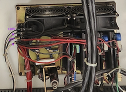
Hey, you are spot on. I realized this late last night as well. The manuals confirm that this series of drives are designed for 120V inputs.I also confirmed that the power supply going to the chassis is a 277V (single leg of 480-3) so it must be that there is a voltage drop, and then, a rectifier before the capacitor. I attached the picture for today's work, but I think there is an SCR directly below the cap, and to its right is the rectifier. I was expecting a transformer and completely missed the SCR hidden behind the wires. I'm trying not to change the wire layout until I am more comfortable, but I think I am getting there. 

So I think the drives have: DC in, DC out, tach, reset/enable and 10V command. 

I do not believe there is a bridge rectifier. I think its just an SCR and then a couple of diodes. Will take apart the wires and check today but I am getting more and more confident that if I identify the 120V input (native to the SD chassis, without the 480V single leg add on) I should be able to connect 120V to it and make it work. Just need to find me a box of 100W lightbulbs. :-)

Please Log in or Create an account to join the conversation.

More
6 months 2 weeks ago - 6 months 2 weeks ago #345642 by motionmasterupgrade
Update on this:
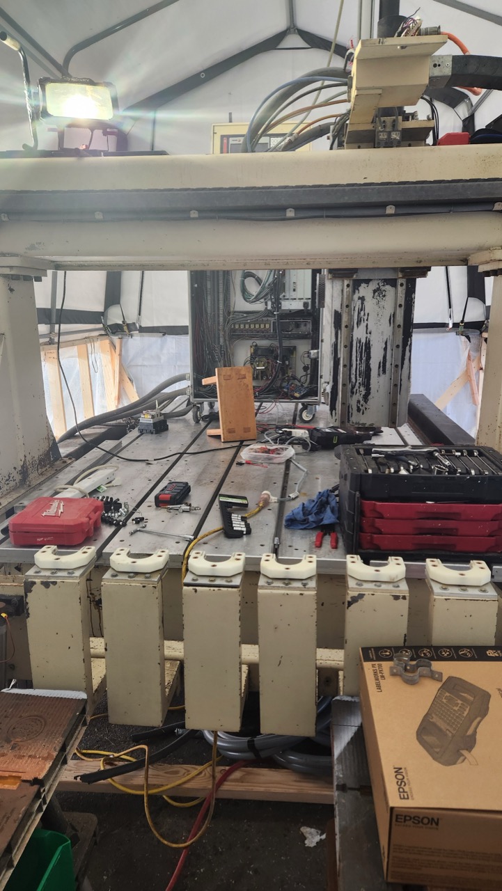
(a) I have connected 220v power to the machine and have confirmed that the drives and servos all work. I will be able to use this machine in its entirely with 220v single phase input on 12HP spindle (will run it at 4hp max) and run all the drives  (8 of them, XYYZ, AA BB). These old amp drives were set up to run the DC brushed servo at max rpm if the signals (10V,tach,EN) were all OPEN - sort of insane. Thankful I had the foresight to disconnect the ballscrews from the servos. I don't have workspace - working ON the bed of the machine with the controller. See pic. Could have been a final destination sort of outcome. 

(b) Hunted down faulty monitor display to a few bad connections and once those were fixed, my LCD display is actually perfectly good, this allowed me to actually test out the machine's ability to work. The linuxcnc mindhive (grumpy old dudes who have forgotted more shit than I will ever learn) helped me out immensely like with everything else. Have to look at the fagor 8055 manual to understand what to expect from triggering the limit switches but other than that, I have a big functioning CNC router. There is some weird stuff going on which I do not understand - the servos are not paired corrected, meaning, moving "controller Y" physically turns one X servo and one Y servo. A few wires need to be fixed and I need to make sure stuff turns in the right direct and get synced and what not. Maybe its a controller setting. I have no intention of using the Fagor controller and will likely not waste time on it. 

(c) Mechanically, Y axis is good. Z axis is good. the X-axis is "grinding". Will remove rust with neutralized citric acid and starch to get me a chelating paste. and repack the bearings on the X axis. I hope it is not a bad ball screw. The blocks that glide on the linear rails are these things that have 2 rows of bearings that slide along the groove. I have no experience whatsoever with these. Any and all tips super appreciated.

(d) Ordered my 5in rotaries. Found this design where the 5in chuck is connected to a wormgear with 20:1 reduction. backlash (10arcs) seems acceptable. The reduction gives me holding power that will all but eliminate any issues with holding the word steady. Adding up the 2 chucks, I'll have in the region of 200Nm of torque on my work pieces. Happy about this. 

(e) Gambling that it will be OK to hang 200lbs off the gantry for the swivel head + spindle. Found some implementations of this with older heavier hardware so I'll take my chances. I might have to upgrade the air balancer, or add a counter weight to the gantry. In any case, its too late. Stuff is ordered and they don't do refunds.

(f) Fun times. The entire manual for my spindle contains one single word of English. It says No! on page 19. See attached. Everything else is in Chinese that I can't read. Hopefully AI translation is decent. Same company with spindle and swivel head. Very happy to have found them. Not pushy. Don't give bullshit answers. Take pride in explaining stuff in engineering speak. Feels like a bunch of guys trying to make the best damn product they are capable of making.

Some questions that remain:
I wonder if I can reuse the dynamic brake and reactors. They are rated for the amperage that I will use with my 9kw spindle. I don't see why not, but I do not know for sure. I also don't understand from first principles what a reactor does. I think they are inductors to smooth out ripples in the outgoing current from VFD to spindle.

Grease. What should I use? I wanted to change the color of the grease so I know which lines are blocked, but someone cautioned against mixing stuff.

Ball bearings. Should I just put new ones in while I'm at it, or, do they last a lifetime? Do I caliper them? Is it even meaningful to? Surely the precision needed would be far more than my 0.02mm caliper. 

July 4th. This has to make a chopstick by then.
 
Last edit: 6 months 2 weeks ago by motionmasterupgrade.

Please Log in or Create an account to join the conversation.
More
6 months 2 weeks ago #345663 by spumco
Replied by spumco on topic MotionMaster Upgrade
Code:
I also don't understand from first principles what a reactor does. I think they are inductors to smooth out ripples in the outgoing current from VFD to spindle

If they're upstream of the VFD they're called 'line reactors' and smooth out incoming power ripples.

If they're downstream they're called 'load reactors' and smooth out the power to the motor.  Reduces heating in the motor, especially useful for older motors which aren't rated for VFD use and which are going to be run at speeds lower than nameplate rating.

Grease - you can flush out all the greased components with kerosene, then blow out excess with air, then regrease with whatever flavor you want.  Disconnect each grease circuit and flush each component separately - this will help identify any clogged or broken lines.  When you've cleared all the individual circuits out, flush any manifolds and header lines.
Code:
the X-axis is "grinding"

Could be from a number of sources.  Suggest disconnecting the ballscrew nut (or nut mount) from the X-carriage.  This will allow you to move the carriage by hand, as well as rotate the ballscrew in it's bearings, and also the nut on the ballscrew.  Should help you identify the source of crunchiness.
Code:
Ball bearings. Should I just put new ones in while I'm at it, or, do they last a lifetime?

Which bearings?  Your machine has quite a few.  Some are cheap, some are not.  Your wallet will determine what you can replace... but if the bearing is easily replaceable and remotely suspect, I'd replace it.  You can usually find NOS name-brand bearings on ebay for decent prices.

Please Log in or Create an account to join the conversation.
More
3 months 4 days ago #348153 by motionmasterupgrade
more update. i haven't posted here must because the discord forum usually helps me with understanding something claude is making up and I'd say I've gotten to the point where the machine is commissioned. half of the problems was just about electrical connections so, note to future self, don't use splices. just wait a day for a new wire to show up and spend that extra 20 bucks. 

so a 5axis retrofit is very doable, but:
(a) pay close attention to the physical properties of the machine. It's very use dependent. If you are carving foam, a direct drive or belt reduction is probably ok, and this actually makes a DIY solution for the physical build quite tenable. I think wood would be fine too if you are carving. For joinery, the precision will most certainly call for a harmonic drive (as in my use case). this means (A) weight, and (B) the weight is about 300mm away from the Z axis guide. There is really no away around this. This then means that your gantry will either need to be fixed, or the there is some counterweight, or, "built like they used to be" (as in my case). I also think Z axis clearance is crucial. Have at least 18in.

That's it really. The rest is kinda sorta a load of wiring because the extra axis adds a lot of wires. Happy to take questions if there are any, but I think I'm safely migrating towards calibration, gui setup, and hopefully, making parts and prospering soon after. so glad I chose this over the other controllers
The following user(s) said Thank You: NWE

Please Log in or Create an account to join the conversation.

Time to create page: 0.141 seconds
Powered by Kunena Forum