- Configuring LinuxCNC
- Configuration Tools
- PnCConf Wizard
- Help needed to get my 7i76E + 7i85S + 7i73 on my mill going.
Help needed to get my 7i76E + 7i85S + 7i73 on my mill going.
- andypugh
-

- Offline
- Moderator
-

Less
More
- Posts: 19852
- Thank you received: 4634
22 Oct 2017 12:41 #100629
by andypugh
Replied by andypugh on topic This post is for "Andypugh"
It would be almost identical with a 7i76. Except that the "encoder.N.." pins become "hm2_5i25.0.encoder.00..." and the VFD outputs become hm2_5i25.0.7i76.0.0.spindir / spinena / spinout.
Please Log in or Create an account to join the conversation.
- zinsade
- Offline
- Junior Member
-

Less
More
- Posts: 20
- Thank you received: 2
23 Oct 2017 20:45 #100697
by zinsade
Replied by zinsade on topic Help needed to get my 7i76E + 7i85S + 7i73 on my mill going.
Hello Andy,
I can not do it.
the following error appears:
>>> hal: 86: signal 'spindle-pwm' of type 'bit' can not add pin 'hm2_5i25.0.7i76.0.0.spinout' of type 'float' <<<
What is wrong?
This is my .hal
best regards
peter
I can not do it.
the following error appears:
>>> hal: 86: signal 'spindle-pwm' of type 'bit' can not add pin 'hm2_5i25.0.7i76.0.0.spinout' of type 'float' <<<
What is wrong?
This is my .hal
# Dateiname = 8AMP-Test-Spindel-vismach.hal
############################################################
#--- 8AMP-Test-Spindel-vismach.hal  ---Stand 2017-10-22 ---#
############################################################
#-----------------------------------------------------------

# HAL config file for vismach simulation of vertical milling machine
# This file deomstrates closed-loop spindle control in both position and
# Velocity modes.

# see http://wiki.linuxcnc.org/cgi-bin/wiki.pl?SpindleOrient for a diagram

# Note that the connections of the signals to "hardware" are all in the
# sim_vmc.hal file rather than here

# First load 2x pid components. These would normally have to be loaded at
# the same time as the Axis PID components

# Initialize the pwmgen ------ nachgetragen
loadrt pwmgen output_type=0
addf pwmgen.update servo-thread
addf pwmgen.make-pulses servo-thread
setp pwmgen.0.pwm-freq 100.0
#setp pwmgen.0.min-dc 0.18
setp pwmgen.0.scale 400
#setp pwmgen.0.dither-pwm true

loadrt pid num_chan=2
addf pid.0.do-pid-calcs servo-thread # Velocity
addf pid.1.do-pid-calcs servo-thread # Position

loadrt orient
addf orient.0 servo-thread

#loadrt mux2 -- This has already been loaded in the sim_vmc.hal
loadrt mux2
addf mux2.0 servo-thread # chooses which pid output goes to the spindle speed control

#Use this to detect that the spindle is oriented
#in the 2.8 release there will be a pin for this as an output of the orient comp
#and the edge-detector is not needed

#loadrt near count=1  (loaded in sim_vmc.hal)
loadrt near count=1
loadrt edge
addf near.0 		servo-thread
addf edge.0         servo-thread
setp edge.0.both 0
setp edge.0.in-edge 0
setp edge.0.out-width-ns 10000000

#----------nachgetragen
# connect the HAL encoder inputs to the real encoder.
net spindle-phase-a encoder.1.phase-A 	<= hm2_5i25.0.encoder.00.input-a
net spindle-phase-b encoder.1.phase-B 	<= hm2_5i25.0.encoder.00.input-b
net spindle-index encoder.1.phase-Z 	<= hm2_5i25.0.encoder.00.input-index


net spindle-pos pid.1.feedback orient.0.position

net spindle-vel 	pid.0.feedback hm2_5i25.0.encoder.00.velocity
net spindle-vel-cmd 	motion.spindle-speed-out pid.0.command
net spindle-vel-pid 	pid.0.output mux2.0.in0

net spindle-pos 	pid.1.feedback orient.0.position near.0.in1 hm2_5i25.0.encoder.00.position
net spindle-pos-cmd 	orient.0.command pid.1.command near.0.in2
net spindle-angle 	motion.spindle-orient-angle orient.0.angle
net spindle-pos-pid 	pid.1.output mux2.0.in1
setp near.0.difference  0.0005
net spindle-in-pos-raw near.0.out edge.0.in #not needed v2.8+, use orient.0.is-oriented
net spindle-in-pos 	edge.0.out motion.spindle-is-oriented

# this switches modes
net orient-mode 	motion.spindle-orient orient.0.enable pid.1.enable mux2.0.sel
net velocity-mode	motion.spindle-on pid.0.enable pwmgen.0.enable
net orient-dir		motion.spindle-orient-mode orient.0.mode

# this is simple for the simulated spindle.
net spindle-cmd 	mux2.0.out

#for a real spindle run by a VFD
loadrt abs count=1
addf abs.0 servo-thread
net spindle-cmd 	mux2.0.out abs.0.in
net spindle-cmd-abs 	abs.0.out pwmgen.0.value
net spindle-pwm 	pwmgen.0.pwm hm2_5i25.0.7i76.0.0.spinout
net spindle-fwd 	abs.0.is-positive hm2_5i25.0.7i76.0.0.spindir

# Tune the PID from the INI values
setp pid.0.Pgain [SPINDLE_9]PGAIN_V
setp pid.0.Igain [SPINDLE_9]IGAIN_V
setp pid.0.Dgain [SPINDLE_9]DGAIN_V
setp pid.0.FF0	 [SPINDLE_9]FF0_V
setp pid.0.FF1   [SPINDLE_9]FF1_V
setp pid.1.Pgain [SPINDLE_9]PGAIN_P
setp pid.1.Igain [SPINDLE_9]IGAIN_P
setp pid.1.Dgain [SPINDLE_9]DGAIN_P
setp pid.1.FF0	 [SPINDLE_9]FF0_P
setp pid.1.FF1   [SPINDLE_9]FF1_P
#-----------------------------------------------------------
best regards
peter
Please Log in or Create an account to join the conversation.
- PCW
-

- Offline
- Moderator
-
Less
More
- Posts: 17853
- Thank you received: 5229
23 Oct 2017 21:23 #100698
by PCW
Replied by PCW on topic Help needed to get my 7i76E + 7i85S + 7i73 on my mill going.
That hal file seems like it came from a parallel port configuration so not really suitable for a 5I25/7I76
I would start with a PNCCONF created configuration for the 5I25/7I76
I would start with a PNCCONF created configuration for the 5I25/7I76
Please Log in or Create an account to join the conversation.
- andypugh
-
- Offline
- Moderator
-
Less
More
- Posts: 19852
- Thank you received: 4634
23 Oct 2017 21:51 #100699
by andypugh
Replied by andypugh on topic Help needed to get my 7i76E + 7i85S + 7i73 on my mill going.
peter: I think the rest is OK, but the spindle pwm is for a parallel port.
Peter: You actually have too _much_ in the HAL file. Delete all references to the pwmgen HAL component, and connect the abs function outputs directly to the 7i76 spindle pins.
You also don't need this section:The only 7i76 encoder pins that you need in the HAL are the position and velocity output pins.
Peter: You actually have too _much_ in the HAL file. Delete all references to the pwmgen HAL component, and connect the abs function outputs directly to the 7i76 spindle pins.
You also don't need this section:
#----------nachgetragen
# connect the HAL encoder inputs to the real encoder.
net spindle-phase-a encoder.1.phase-A 	<= hm2_5i25.0.encoder.00.input-a
net spindle-phase-b encoder.1.phase-B 	<= hm2_5i25.0.encoder.00.input-b
net spindle-index encoder.1.phase-Z <= hm2_5i25.0.encoder.00.input-indexPlease Log in or Create an account to join the conversation.
- tecno
-
 Topic Author
- Offline
- Platinum Member
-

Less
More
- Posts: 1850
- Thank you received: 127
21 Dec 2017 18:57 #103440
by tecno
Replied by tecno on topic Help needed to get my 7i76E + 7i85S + 7i73 on my mill going.
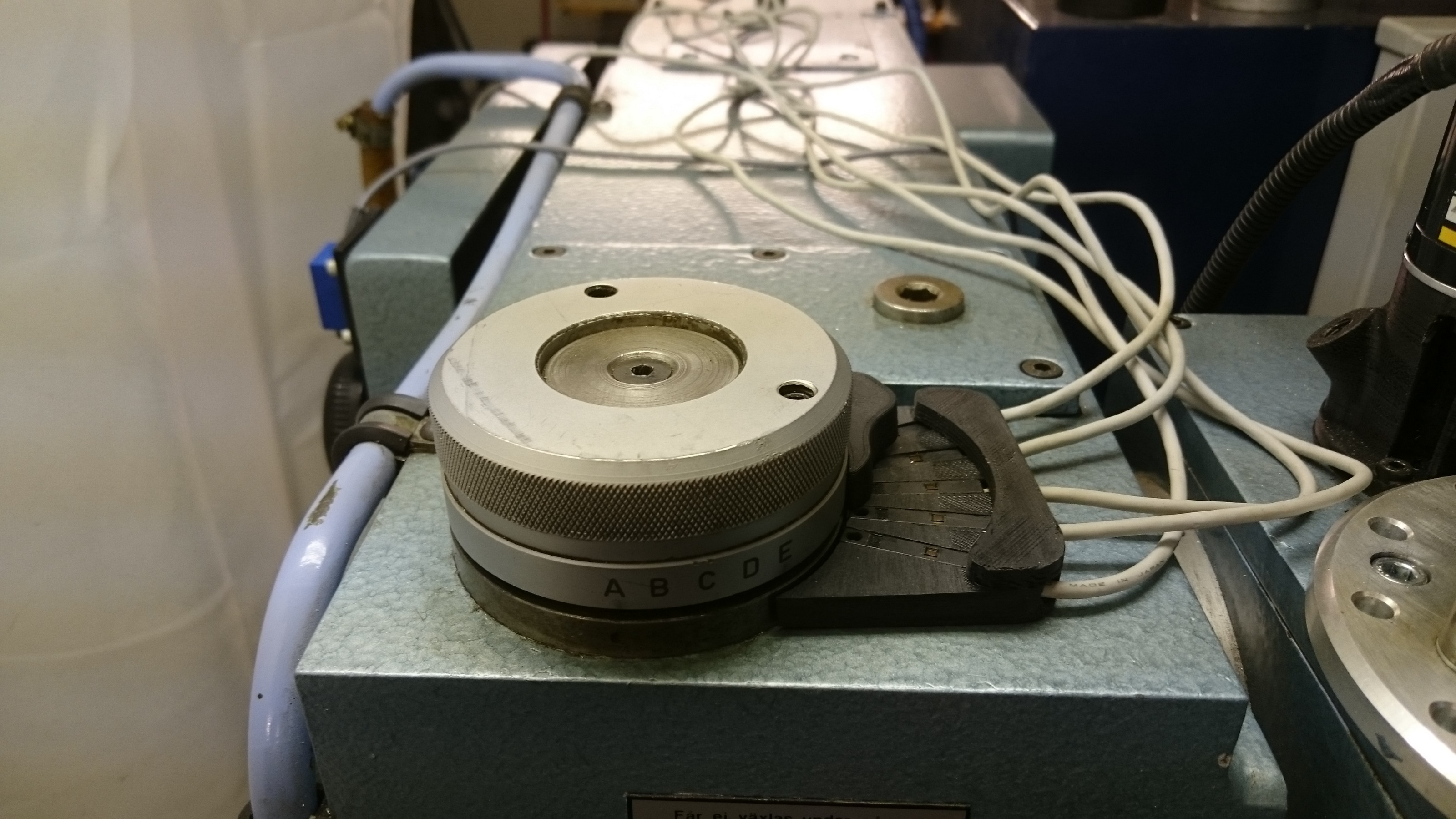
Have today 3D printed some parts for the gearbox discussed earlier.
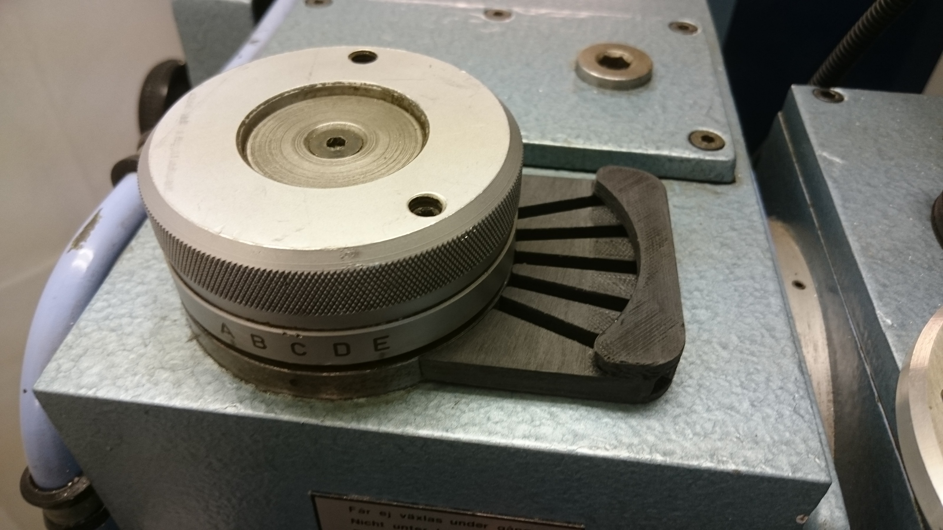
Will be glued to housing
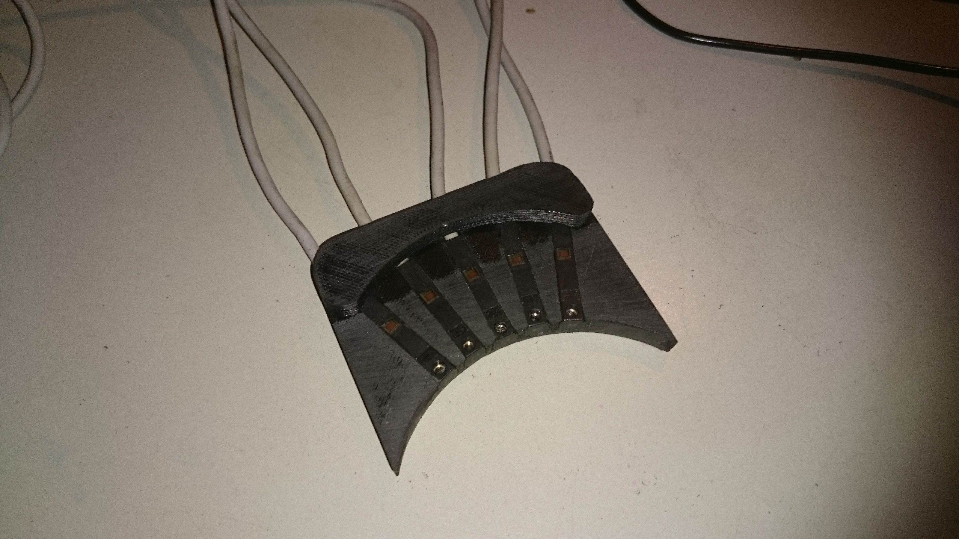
SMC D-Y7P
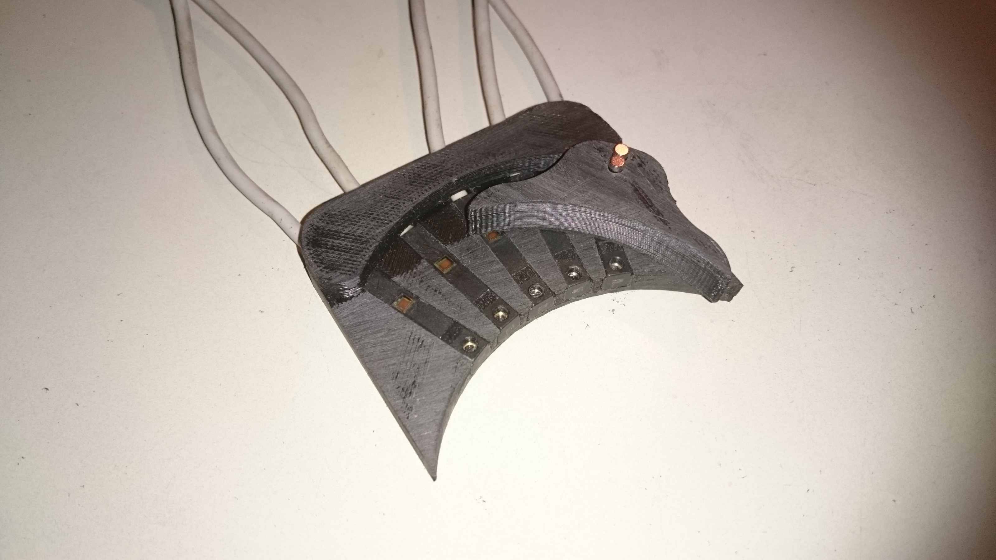
Arm to be glued on selector.
Will try to get the inductive sensor for Hi/Lo gear fixed hopefully tomorrow.
Will be glued to housing
SMC D-Y7P
Arm to be glued on selector.
Will try to get the inductive sensor for Hi/Lo gear fixed hopefully tomorrow.
Please Log in or Create an account to join the conversation.
- rodw
-

- Offline
- Platinum Member
-
Less
More
- Posts: 11875
- Thank you received: 4027
21 Dec 2017 21:39 #103442
by rodw
Replied by rodw on topic Help needed to get my 7i76E + 7i85S + 7i73 on my mill going.
Looks nice!
Please Log in or Create an account to join the conversation.
- tecno
-
Topic Author
- Offline
- Platinum Member
-
Less
More
- Posts: 1850
- Thank you received: 127
21 Dec 2017 21:44 #103443
by tecno
Replied by tecno on topic Help needed to get my 7i76E + 7i85S + 7i73 on my mill going.
Gday Rod, thanks.
I hope it will serve me well.
I hope it will serve me well.
Please Log in or Create an account to join the conversation.
- tecno
-
Topic Author
- Offline
- Platinum Member
-
Less
More
- Posts: 1850
- Thank you received: 127
22 Dec 2017 17:03 #103461
by tecno
Replied by tecno on topic Help needed to get my 7i76E + 7i85S + 7i73 on my mill going.
So now also Hi / Lo gear detector in place. Using Contrinex LHK-3031-303 with adjustable 'focus'.
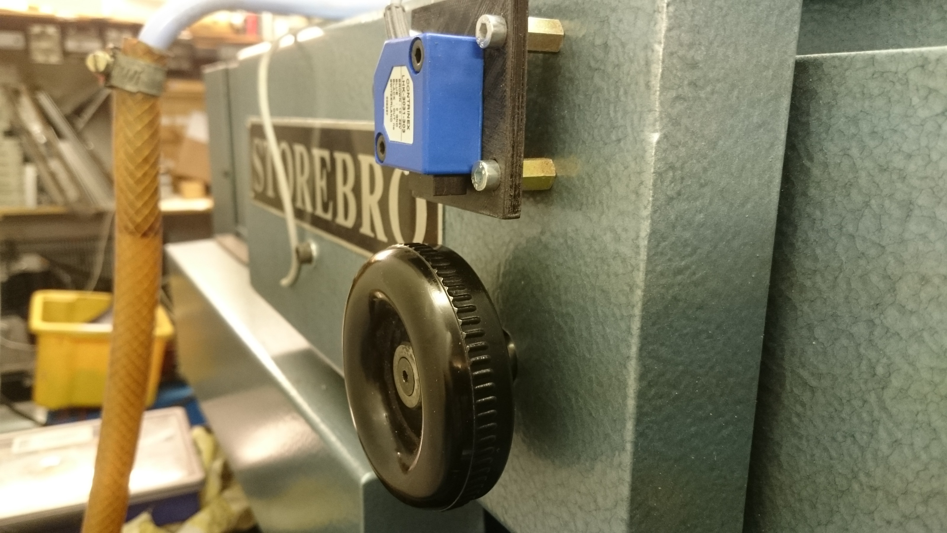
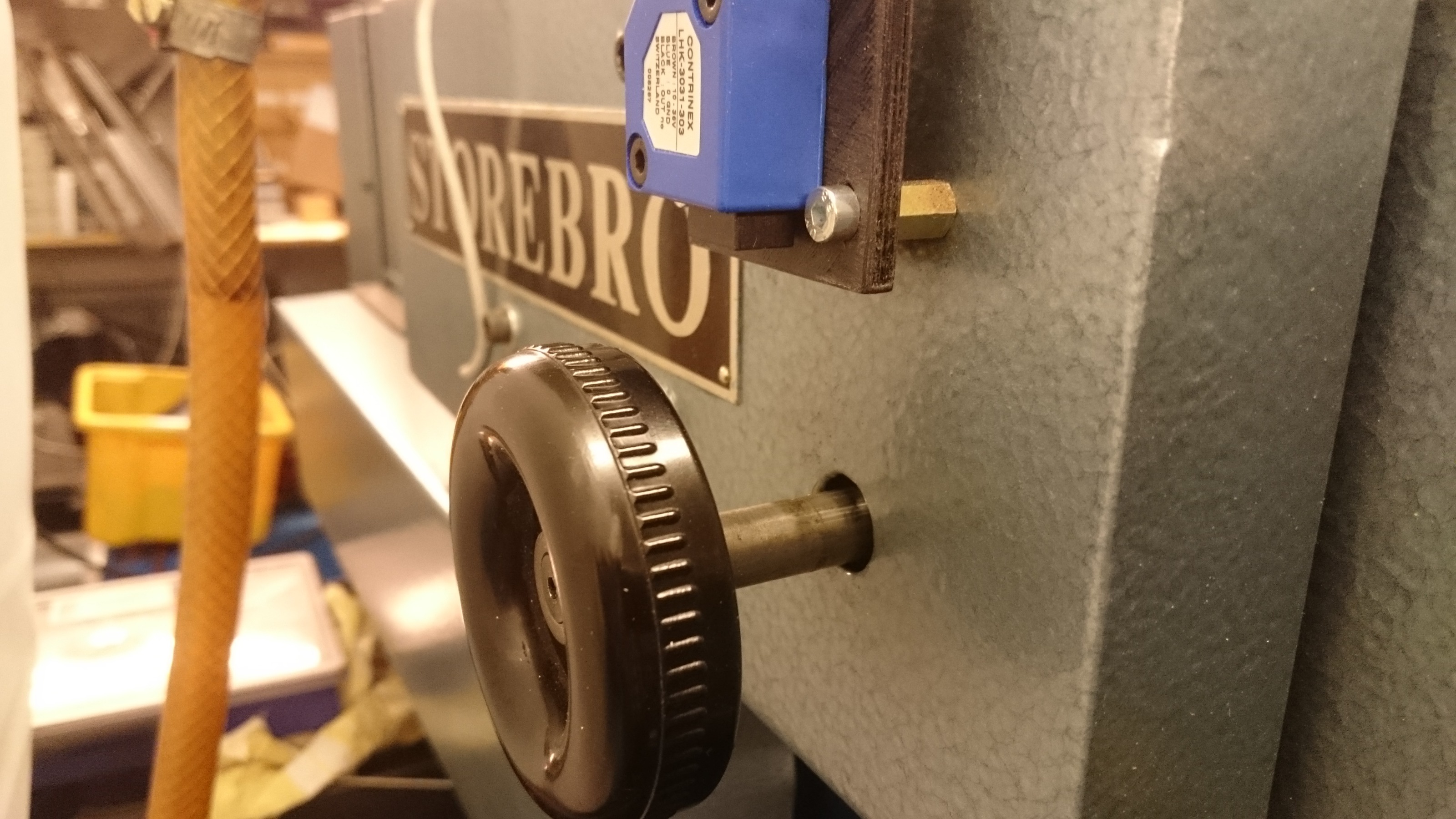
Time to install the cables to a RJ45 connector
Time to install the cables to a RJ45 connector
Please Log in or Create an account to join the conversation.
- tecno
-
Topic Author
- Offline
- Platinum Member
-
Less
More
- Posts: 1850
- Thank you received: 127
23 Dec 2017 16:40 #103487
by tecno
Replied by tecno on topic Help needed to get my 7i76E + 7i85S + 7i73 on my mill going.
Cabling ready and tested so now it is time to tinker how to get this all working.
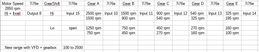
With above I get 100 to 2500 rpm, spindle motor fixed to high speed = 2850 rpm and Hi / Lo + Gears A to E.
So what would be the best way to get this working? Yes there are combinations of settings allowing two ranges.
Any pointers on what to read?
With above I get 100 to 2500 rpm, spindle motor fixed to high speed = 2850 rpm and Hi / Lo + Gears A to E.
So what would be the best way to get this working? Yes there are combinations of settings allowing two ranges.
Any pointers on what to read?
Please Log in or Create an account to join the conversation.
- rodw
-
- Offline
- Platinum Member
-
Less
More
- Posts: 11875
- Thank you received: 4027
23 Dec 2017 17:11 #103488
by rodw
Replied by rodw on topic Help needed to get my 7i76E + 7i85S + 7i73 on my mill going.
Have a look at lut5 as that gives you 5 bits of input. Its pretty cryptic but I am sure Andy will help you. He's the expert on it.
I think once you resolve lut 5 to a speed, you should be able to use a mux2 to multiply the result by 1 or 2 depending on the hi/lo gear selection.
I think once you resolve lut 5 to a speed, you should be able to use a mux2 to multiply the result by 1 or 2 depending on the hi/lo gear selection.
Please Log in or Create an account to join the conversation.
Moderators: cmorley
- Configuring LinuxCNC
- Configuration Tools
- PnCConf Wizard
- Help needed to get my 7i76E + 7i85S + 7i73 on my mill going.
Time to create page: 0.468 seconds