PNCConf Config (Think Im missing something)
- Type_Zero_Design
- Offline
- Premium Member
-

Less
More
- Posts: 133
- Thank you received: 7
12 May 2019 05:35 #133507
by Type_Zero_Design
PNCConf Config (Think Im missing something) was created by Type_Zero_Design
Alright Guys,
I think I am just totally missing something here....
Running2.8 on stretch
Trying to setup 7176e atm but also have 7i85 but dont have a clue where to begin to add that...
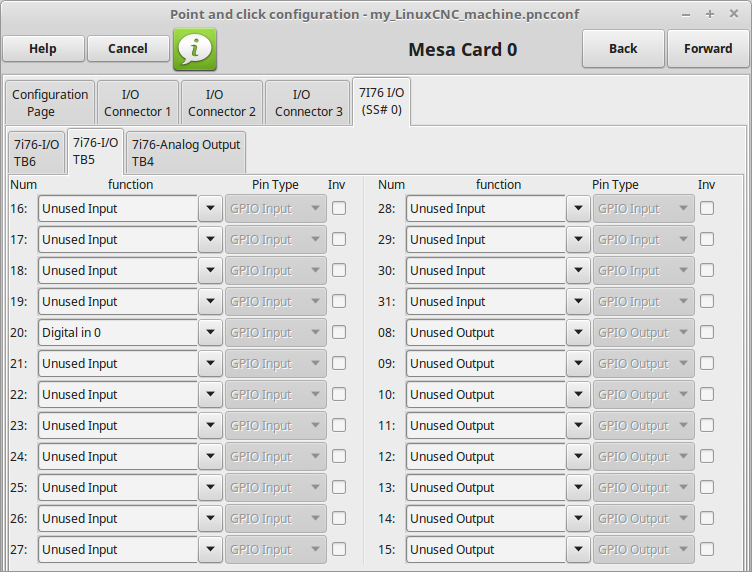
I make it to the I/O portion and I am just completely lost.
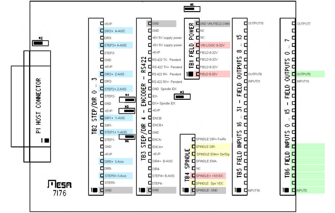
What are the connectors? Are they related to the actual physical connectors on the board like TB1 TB2 ect?
What are the pin numbers? Are they related to physical Pins on the board?
If the pins are not physical pins is there some ryme or reason to what connectors/pins I should assign my I/O ect. to?
once I assign my step gens and skip to the next page, basically everything is grayed out on the motor/encoder config
Also is something supposed to happen when I click the launch test panel button?
Maybe I am over thinking this but I am just lost.
Sorry for the barrage of ignorant questions but I have spent most of the day googling and reading this forum but I feel more confused then when I started, Though I will say everyone here has been extremely helpful!
Please Log in or Create an account to join the conversation.
- InMyDarkestHour
-

- Visitor
-

12 May 2019 07:17 #133514
by InMyDarkestHour
Replied by InMyDarkestHour on topic PNCConf Config (Think Im missing something)
Did you come along this thread ?
forum.linuxcnc.org/39-pncconf/34018-pncc...25-7i76-7i85?start=0
forum.linuxcnc.org/39-pncconf/34018-pncc...25-7i76-7i85?start=0
Please Log in or Create an account to join the conversation.
- rodw
-

- Online
- Platinum Member
-

Less
More
- Posts: 11717
- Thank you received: 3964
12 May 2019 11:24 #133550
by rodw
Replied by rodw on topic PNCConf Config (Think Im missing something)
For a 7i76e, this is a better guide
forum.linuxcnc.org/27-driver-boards/3191...ection-sheet?start=0
All I've ever done is load up halshow and look for the pins I need. But if you look at the 7i76e manual all of the pins are listed in order and matched against the physical port number
I made up a table listing the physical pin (eg TB6-05), the signal (Input 04) and where its connected (gantry Y min limit)
Please Log in or Create an account to join the conversation.
- Type_Zero_Design
- Offline
- Premium Member
-

Less
More
- Posts: 133
- Thank you received: 7
15 May 2019 00:56 #133798
by Type_Zero_Design
Replied by Type_Zero_Design on topic PNCConf Config (Think Im missing something)
I feel like i'm completely missing something... How do you determine what physical terminal relates to what pin in PNC Config?
I see the listings in the manual for what signal is at what terminal I just don't understand what the numbering convention in PNC Config is referring to?
I appreciate any info!
I see the listings in the manual for what signal is at what terminal I just don't understand what the numbering convention in PNC Config is referring to?
I appreciate any info!
Please Log in or Create an account to join the conversation.
- cmorley
- Away
- Moderator
-

Less
More
- Posts: 7286
- Thank you received: 2125
15 May 2019 02:09 #133800
by cmorley
Replied by cmorley on topic PNCConf Config (Think Im missing something)
Attachments:
Please Log in or Create an account to join the conversation.
- Type_Zero_Design
- Offline
- Premium Member
-

Less
More
- Posts: 133
- Thank you received: 7
15 May 2019 02:23 #133802
by Type_Zero_Design
Replied by Type_Zero_Design on topic PNCConf Config (Think Im missing something)
So Chris,how would I identify say input 20? I see it is on terminal 5 on TB5 on the board, but How would I identify in in PNC Config?
Please Log in or Create an account to join the conversation.
- cmorley
- Away
- Moderator
-

Less
More
- Posts: 7286
- Thank you received: 2125
15 May 2019 02:32 #133803
by cmorley
Replied by cmorley on topic PNCConf Config (Think Im missing something)
Attachments:
The following user(s) said Thank You: Type_Zero_Design
Please Log in or Create an account to join the conversation.
- Type_Zero_Design
- Offline
- Premium Member
-

Less
More
- Posts: 133
- Thank you received: 7
15 May 2019 02:41 #133805
by Type_Zero_Design
Replied by Type_Zero_Design on topic PNCConf Config (Think Im missing something)
Shit!
I feel like an idiot!
I just found the 7i76 tab Under the I/O with each connector. I have been looking at the I/O connector tabs this whole time.
So what are the I/O connector 1-3
Getting there but still confused,,,,
I feel like an idiot!
I just found the 7i76 tab Under the I/O with each connector. I have been looking at the I/O connector tabs this whole time.
So what are the I/O connector 1-3
Getting there but still confused,,,,
Please Log in or Create an account to join the conversation.
- cmorley
- Away
- Moderator
-

Less
More
- Posts: 7286
- Thank you received: 2125
15 May 2019 02:47 #133807
by cmorley
Replied by cmorley on topic PNCConf Config (Think Im missing something)
I/O 1 is for the step generators.
I/O 2 and 3 are for the expansion connectors.
Chris M
I/O 2 and 3 are for the expansion connectors.
Chris M
Please Log in or Create an account to join the conversation.
- Type_Zero_Design
- Offline
- Premium Member
-

Less
More
- Posts: 133
- Thank you received: 7
15 May 2019 03:09 - 15 May 2019 03:14 #133808
by Type_Zero_Design
Replied by Type_Zero_Design on topic PNCConf Config (Think Im missing something)
Chris Thank you!!! I missed that whole tab somehow
So say I want to hook an encoder to TB3 as depicted in Norberts wiring diagram at this link:
forum.linuxcnc.org/27-driver-boards/3191...ection-sheet?start=0
It looks like it would be under I/O 1 and I just search for the actual signal name?
But then that Idea seems to fall apart when looking for the spindle connections on TB4. Unless they are just fixed and dont need to be assigned? ******EDIT: TB4 is under 7i76 tab*******
Sorry for all the questions.
Last edit: 15 May 2019 03:14 by Type_Zero_Design.
Please Log in or Create an account to join the conversation.
Moderators: cmorley
Time to create page: 0.267 seconds


