Labview UI project for Linuxcnc
- pl7i92
-

- Offline
- Platinum Member
-

Less
More
- Posts: 1872
- Thank you received: 358
01 Sep 2019 06:56 #143759
by pl7i92
Replied by pl7i92 on topic Labview UI project for Linuxcnc
this will get into a real new system
WHERE is C Axis in the testgui
only 8 from 9 Axis present
WHERE is C Axis in the testgui
only 8 from 9 Axis present
Please Log in or Create an account to join the conversation.
- auto-mation-assist
-
Topic Author
- Offline
- Platinum Member
-

Less
More
- Posts: 425
- Thank you received: 81
01 Sep 2019 14:53 - 01 Sep 2019 15:32 #143782
by auto-mation-assist
Replied by auto-mation-assist on topic Labview UI project for Linuxcnc
The C axis display was left out by error before and was corrected shortly after posting. It was actually processing the C axis position data, just not displaying it. I'm pleased that you noticed this.
That particular test setup for status data is not available anymore and was re-coded into the below picture.
It automatically connects to LinuxCnc and designed to pass status data to other user processes that require its data.
That particular test setup for status data is not available anymore and was re-coded into the below picture.
It automatically connects to LinuxCnc and designed to pass status data to other user processes that require its data.
Attachments:
Last edit: 01 Sep 2019 15:32 by auto-mation-assist. Reason: Added picture
Please Log in or Create an account to join the conversation.
- auto-mation-assist
-
Topic Author
- Offline
- Platinum Member
-

Less
More
- Posts: 425
- Thank you received: 81
03 Sep 2019 06:09 - 03 Sep 2019 06:12 #144051
by auto-mation-assist
Replied by auto-mation-assist on topic Labview UI project for Linuxcnc
All my testing involved sending commands from my Windows development computer to my Linux Mint computer over TCP to port 5005 via hex encoded commands and getting status info back. I have sufficient commands working now to actually start work on building them into my Labview based Gui. The GUI itself is coded as a event driven state-machine.
The commands I have working and verified are:
Estop
Estop reset
Power on
Power off
Manual mode selection
Auto mode selection
Mdi mode selection
Jog stop for continuous jog mode
Traj scale scale set
Teleop mode selection
Continuous jog mode
Incremental jog mode
Spindle selection by number along with speed and directional control
I think enough to get basic machine functions working from the gui.
I will need to think a bit on how to best implement sending commands but this will likely use arrays or clusters or a combination of both.
Have not had much time to spent on decoding the status info yet but the data for the Dro's data is properly decoded so that I can monitor movement when ready to test further. I'm hoping that there is a map or at least part of a map of the status data returned from a status request somewhere. A small hint can help a lot and it would save a lot of time.
Last edit: 03 Sep 2019 06:12 by auto-mation-assist.
The following user(s) said Thank You: rodw
Please Log in or Create an account to join the conversation.
- auto-mation-assist
-
Topic Author
- Offline
- Platinum Member
-

Less
More
- Posts: 425
- Thank you received: 81
03 Sep 2019 19:36 - 03 Sep 2019 21:27 #144079
by auto-mation-assist
Replied by auto-mation-assist on topic Labview UI project for Linuxcnc
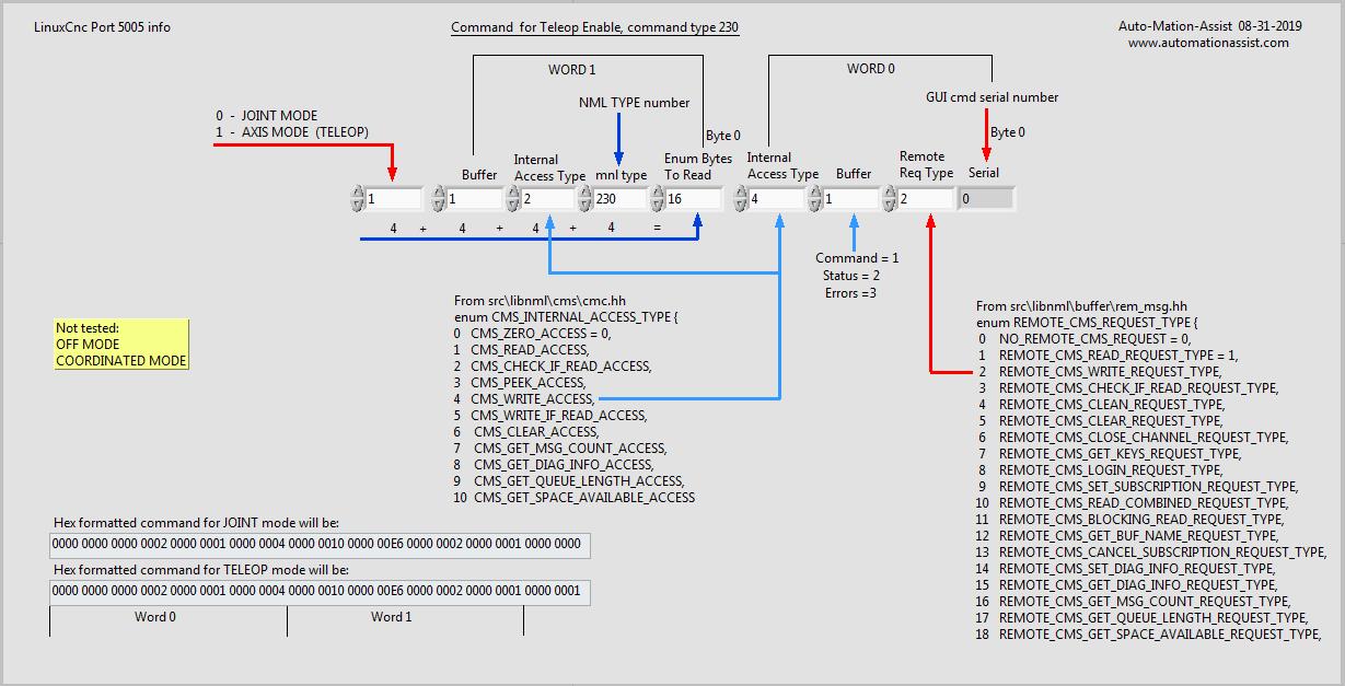
Here the map I'm using for the TELEOP mode changes right now.
Improper TELEOP mode will prevent some actions from being available. Once such case is not being in joint mode during joint specific homing.
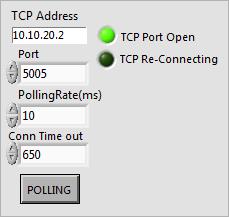
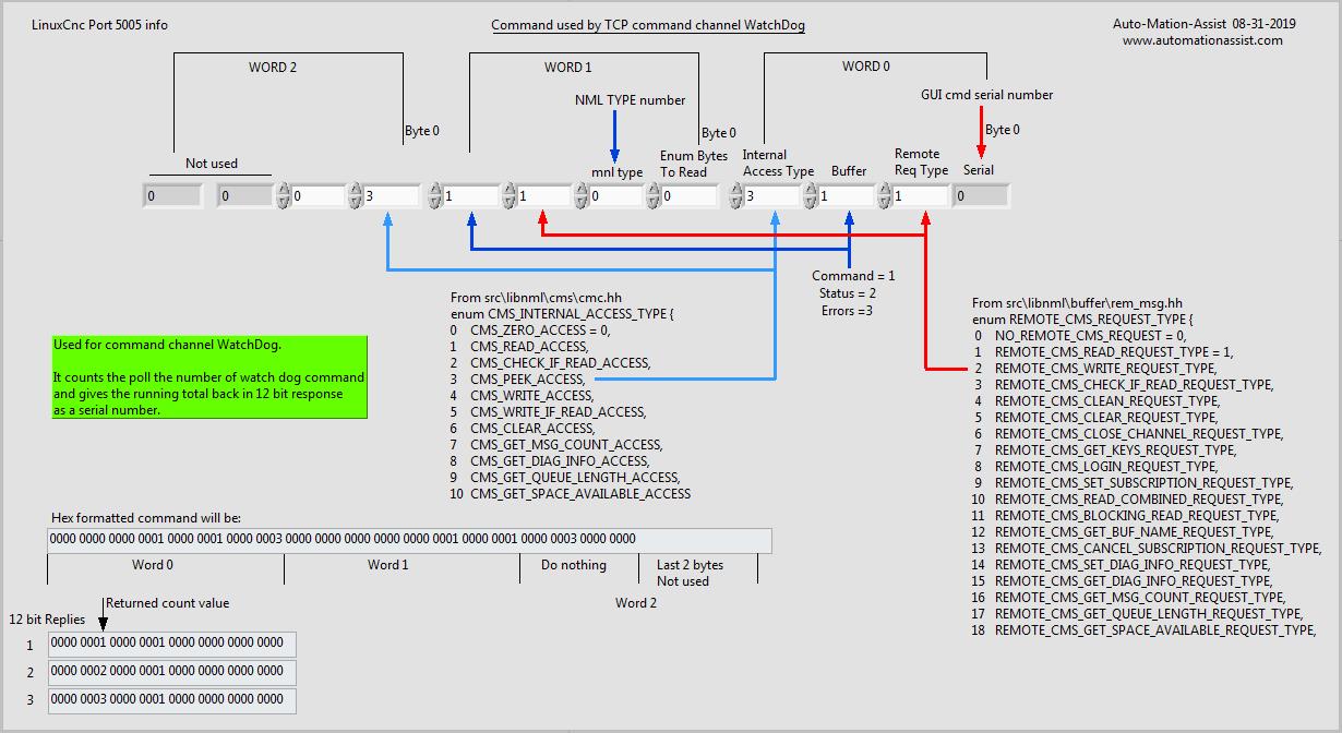
I have started work on the network interface code for the command channel. This is uses the same code as the status channel network interface with only minor changes (which has been fully tested already). The command channel does need a WatchDog feature and I have that running right now on the command channel. It is over 800000 WatchDog polling request now with no problems noted.
To speed testing up I raised the normal expected rate of once per second to 10ms for testing purposes in the above note. The command channel watchdog returns 12 bits of data with the serial number of the WatchDog command. Then immediately adds 1 and sends 12 more bits and returns serial number plus 1. Thus this is a paired response and can be decoded as 24 bits as below..
The number at bit location 0, length 4 is equal to the WatchDog sent serial number that was sent. The serial number returned at bit location 12, length 4 needs to be divided by two to get the sent serial number of the WatchDog command.
This is the command map for command channel WatchDog polling.
Attachments:
Last edit: 03 Sep 2019 21:27 by auto-mation-assist. Reason: Added: Serial number divide by two note.
Please Log in or Create an account to join the conversation.
- auto-mation-assist
-
Topic Author
- Offline
- Platinum Member
-

Less
More
- Posts: 425
- Thank you received: 81
04 Sep 2019 03:56 - 04 Sep 2019 03:58 #144119
by auto-mation-assist
Replied by auto-mation-assist on topic Labview UI project for Linuxcnc
In getting the feel of how fast LinuxCnc can handle commands from the network without running into some NML queue issues I found that my normal execution rate of LinuxCnc had to be increased. Thus in the .ini file under [EMCIO] Cycle time was decreased from 0.100 to 0.001 which is still pretty slow for modern computers.
This change allowed sending 500 mist on/off commands which is convenient for testing at the change rate of 10ms without running into queue issues and delay of command execution. At the original rate it was possible to send three of the same commands at approximately 30ms intervals and run into an occasional problem of data backing up in the NML queue.
I have pushed enough commands at a 100ms change rate to cause the queue minutes to empty. This had no ill effect during testing other than the execution of the commands being delayed by a long time. They all appeared to execute.
Last edit: 04 Sep 2019 03:58 by auto-mation-assist.
Please Log in or Create an account to join the conversation.
- auto-mation-assist
-
Topic Author
- Offline
- Platinum Member
-

Less
More
- Posts: 425
- Thank you received: 81
09 Sep 2019 05:34 - 09 Sep 2019 05:39 #144561
by auto-mation-assist
Replied by auto-mation-assist on topic Labview UI project for Linuxcnc
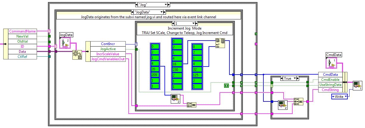
I think there many who have never seen Labview code so I have attached a screen shot of part of my code that handles sending commands to LinuxCnc to TCP port 5005. This one is for final command encoding for Jogging in linear continuous and Incremental modes. The term Vi used in the text below refers to virtual instruments and is used extensively in Labview.
The data arrives from the Gui's Subpanel Vi's on the left via a cluster that contains the values of variables that jogging buttons area coded to create when selected. This data is decoded from other data and separated out via the name 'Jog' and then further in to the actual data.
After this you can see the NML Hex coded commands in green. These are arrays. They are coded for NML types 209, 230 and 125. The type 209 and 230 require external data along with the contents of the arrays. The continuous jog mode is handled by case selection 0 in a similar way. It uses NML types 230,124 and 136. Type 136 being the Jog stop command.
The part on the very right sends data from the command generator section to the Sub Vi that does the actual talking to LinuxCnc command link at TCP port 5005.
The jogging part is completely operational now and the Milling machine is responding all jogging commands perfectly.
The below is part of my Labview command encoder function and is a picture of part of the actual code.
Attachments:
Last edit: 09 Sep 2019 05:39 by auto-mation-assist.
The following user(s) said Thank You: phillc54, snoozer77
Please Log in or Create an account to join the conversation.
- pl7i92
-

- Offline
- Platinum Member
-

Less
More
- Posts: 1872
- Thank you received: 358
09 Sep 2019 13:05 #144602
by pl7i92
Replied by pl7i92 on topic Labview UI project for Linuxcnc
did you get any movment so far
Please Log in or Create an account to join the conversation.
- auto-mation-assist
-
Topic Author
- Offline
- Platinum Member
-

Less
More
- Posts: 425
- Thank you received: 81
09 Sep 2019 17:22 #144616
by auto-mation-assist
Replied by auto-mation-assist on topic Labview UI project for Linuxcnc
Yes. Jogging in continuous and incremental modes move the machines axis properly in both positive and negative directions.
Please Log in or Create an account to join the conversation.
- auto-mation-assist
-
Topic Author
- Offline
- Platinum Member
-

Less
More
- Posts: 425
- Thank you received: 81
09 Sep 2019 17:39 - 09 Sep 2019 17:44 #144618
by auto-mation-assist
Replied by auto-mation-assist on topic Labview UI project for Linuxcnc
Since it is likely that the command arrays of the same type will be used in multiple locations the command arrays will be changed to 'type defines'.
Type defines in Labview have a name extension name of .ctl and If changes are made to a type define then each location that uses it will be automatically updated to match and thus save a lot potential future code editing if changes to a command are required.
Type defines in Labview have a name extension name of .ctl and If changes are made to a type define then each location that uses it will be automatically updated to match and thus save a lot potential future code editing if changes to a command are required.
Last edit: 09 Sep 2019 17:44 by auto-mation-assist. Reason: Removed the word 'so'
Please Log in or Create an account to join the conversation.
- auto-mation-assist
-
Topic Author
- Offline
- Platinum Member
-

Less
More
- Posts: 425
- Thank you received: 81
10 Sep 2019 06:50 #144671
by auto-mation-assist
Replied by auto-mation-assist on topic Labview UI project for Linuxcnc
I programmed in the following into my command encoder; flood on and off , mist on and off , lube on and off, estop, estop reset, power on and off, manual mode, mdi mode, auto mode, abort, continuous and incremental jogging functions so far. All are working now from my Labview Gui buttons and Linuxcnc is responding properly.
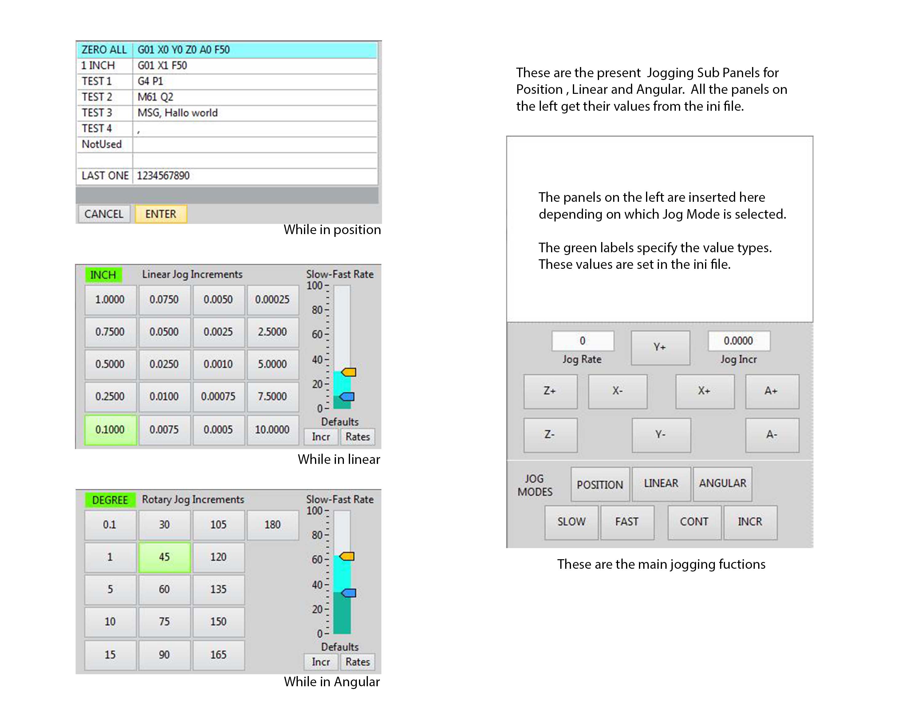
I will work on the spindle controls next and after that will do some testing with the position jogging functions which are available from a list in the position subpanel in the jogging section. It gets its list from the .ini file. As do all the button values for linear and angular jogging. Separate list is used for mm and inch modes.
This is a picture of the jogging buttons and position command list that I used for testing in the past.
Attachments:
The following user(s) said Thank You: tommylight
Please Log in or Create an account to join the conversation.
Time to create page: 0.255 seconds

