Mach3 5 Axis China BoB: 5 V Versorgung
- pl7i92
-

- Offline
- Platinum Member
-

Less
More
- Posts: 1872
- Thank you received: 358
05 Oct 2019 09:39 #147176
by pl7i92
Replied by pl7i92 on topic Mach3 5 Axis China BoB: 5 V Versorgung
warumm nutzt du denn nicht einen einfachen stepdown wandler
LM65xx reicht
oben linke im bild
12V und 5V
a 2Euro

LM65xx reicht
oben linke im bild
12V und 5V
a 2Euro
Attachments:
Please Log in or Create an account to join the conversation.
- Mike_Eitel
-

- Offline
- Platinum Member
-
Less
More
- Posts: 1052
- Thank you received: 183
05 Oct 2019 09:52 #147179
by Mike_Eitel
Replied by Mike_Eitel on topic Mach3 5 Axis China BoB: 5 V Versorgung
General:
Printer port works with 5v but has no +5v supply on the plugs.
The ic's getting signals from pc to drive the step/dir need a supply(5v best)
The easiest way for the manufacturer is to have USB port so there 5v can be feed in. Me personally preferes to get them from pc supply. (There ares different ways to do it, using a double typ A cabe is easiest. And as the stepper drivers are normally quite neat to the job and also galvanic isolated 5v are emv save enough.
Another story is the reading of contacts. They are influenced by higher emv as longer distances are requested. I've only seen them realized by optocouplers. Therefore u need a second and better higher voltage. That's why you always find additional borns to supply external +. ( Also used to allow a 0-10v output swing, that would otherwise not be cheapo to do)
The grounding is a bit of philosophy. As boards are often cheepo, both negative supplies are often connected so you have no choice anyhow. But that means you easily run a "ground loop" over external supply and printer/USB cable. So try to keep these cables near to each other's.
Myself if the hw allows I always connect negative to ground only via a resistor in parrallel with a capacitor. One time to avoid high current low frequency mass loops with higher frequency short gutted and on the other side gives that the possibility to measure on the resistor if something is not good in your cabling or electronic.
If you understand these things it is not to difficult to "re-engineer" a cheapo job without good documentation.
m5c Mike
The following user(s) said Thank You: Louis Cypher
Please Log in or Create an account to join the conversation.
- Louis Cypher
- Offline
- Senior Member
-

Less
More
- Posts: 45
- Thank you received: 0
06 Oct 2019 16:18 - 06 Oct 2019 16:46 #147255
by Louis Cypher
Replied by Louis Cypher on topic Mach3 5 Axis China BoB: 5 V Versorgung
Wovon? Von der E-Box? Diagramm ist oben
Ist noch nicht viel zu sehen
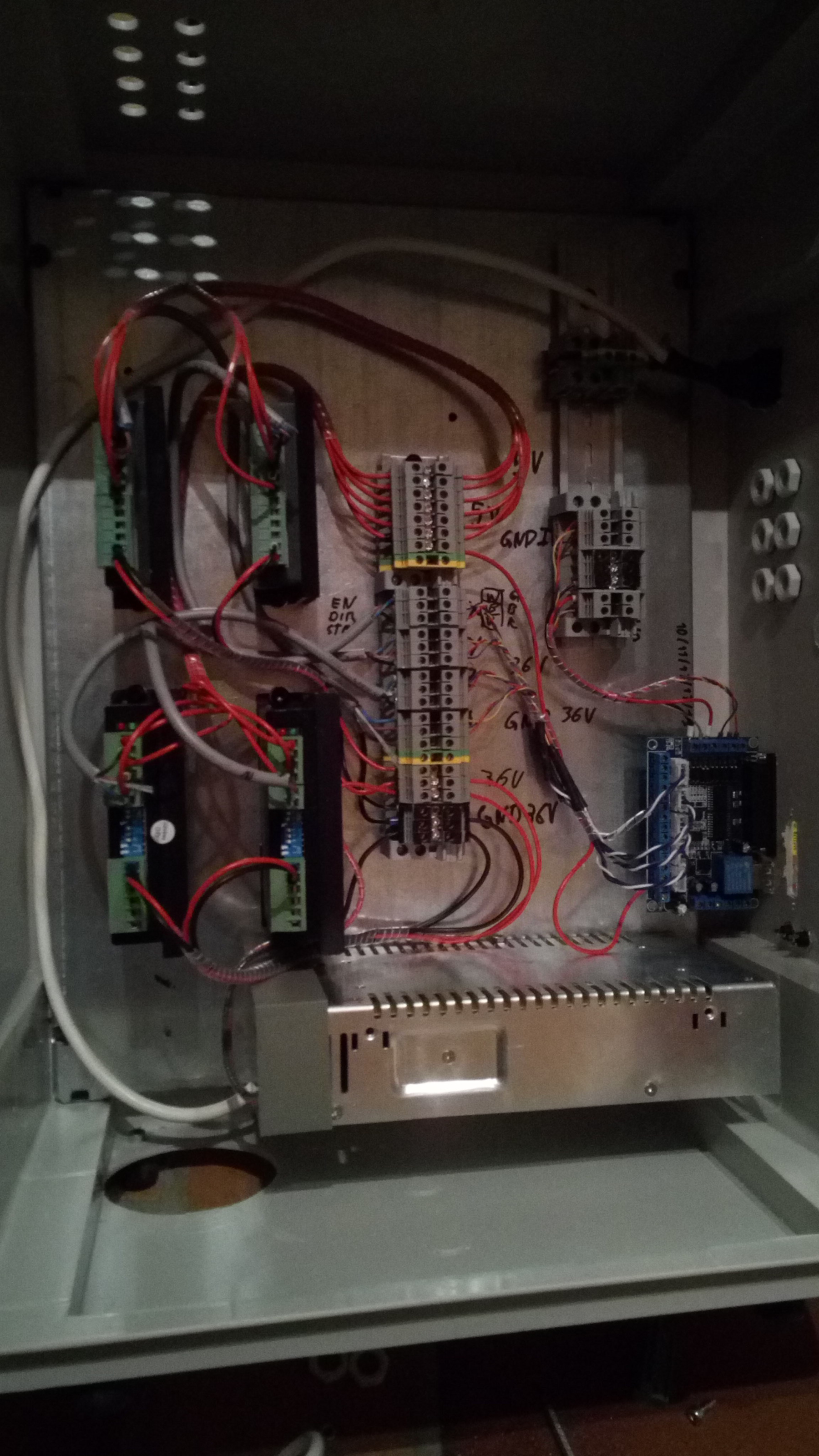
Ist noch nicht viel zu sehen
Attachments:
Last edit: 06 Oct 2019 16:46 by Louis Cypher. Reason: Added image
Please Log in or Create an account to join the conversation.
- Louis Cypher
- Offline
- Senior Member
-
Less
More
- Posts: 45
- Thank you received: 0
06 Oct 2019 16:31 #147259
by Louis Cypher
Basically you are saying you have one circuit for the endstops running at a higher voltage and a board with optocouplers close to the bob to reduce EMV?
I measured the board/drivers and ground doesn't seem to be connected in the drivers. Same for endstop circuit vs digital IO part of the bob
Replied by Louis Cypher on topic Mach3 5 Axis China BoB: 5 V Versorgung
Another story is the reading of contacts. They are influenced by higher emv as longer distances are requested. I've only seen them realized by optocouplers. Therefore u need a second and better higher voltage.
Basically you are saying you have one circuit for the endstops running at a higher voltage and a board with optocouplers close to the bob to reduce EMV?
The grounding is a bit of philosophy. As boards are often cheepo, both negative supplies are often connected so you have no choice anyhow. But that means you easily run a "ground loop" over external supply and printer/USB cable. So try to keep these cables near to each other's.
I measured the board/drivers and ground doesn't seem to be connected in the drivers. Same for endstop circuit vs digital IO part of the bob
Any values you can give me for the capacitor? I was thinking about a 1k to 10k resistor to keep the current in the mA range.Myself if the hw allows I always connect negative to ground only via a resistor in parrallel with a capacitor. One time to avoid high current low frequency mass loops with higher frequency short gutted and on the other side gives that the possibility to measure on the resistor if something is not good in your cabling or electronic.
If you understand these things it is not to difficult to "re-engineer" a cheapo job without good documentation.
m5c Mike
Please Log in or Create an account to join the conversation.
- Louis Cypher
- Offline
- Senior Member
-
Less
More
- Posts: 45
- Thank you received: 0
06 Oct 2019 16:35 - 06 Oct 2019 16:36 #147261
by Louis Cypher
Replied by Louis Cypher on topic Mach3 5 Axis China BoB: 5 V Versorgung
Der Step Down Converter hat wahrscheinlich einen gemeinsamen Ground für Input und Output Seite. Damit baust Du einen Groundloop von der Hochstromseite der Treiber zur Digitalseite der Treiber. Ich habe mich mit einem Digitalelektroniker unterhalten und der hat mir das bestätigt und deutlich davon abgeraten. Deswegen arbeite ich lieber über einen extra Powersupply.warumm nutzt du denn nicht einen einfachen stepdown wandler
Last edit: 06 Oct 2019 16:36 by Louis Cypher. Reason: No need to have the picture in this post
Please Log in or Create an account to join the conversation.
- Louis Cypher
- Offline
- Senior Member
-
Less
More
- Posts: 45
- Thank you received: 0
06 Oct 2019 17:46 #147276
by Louis Cypher
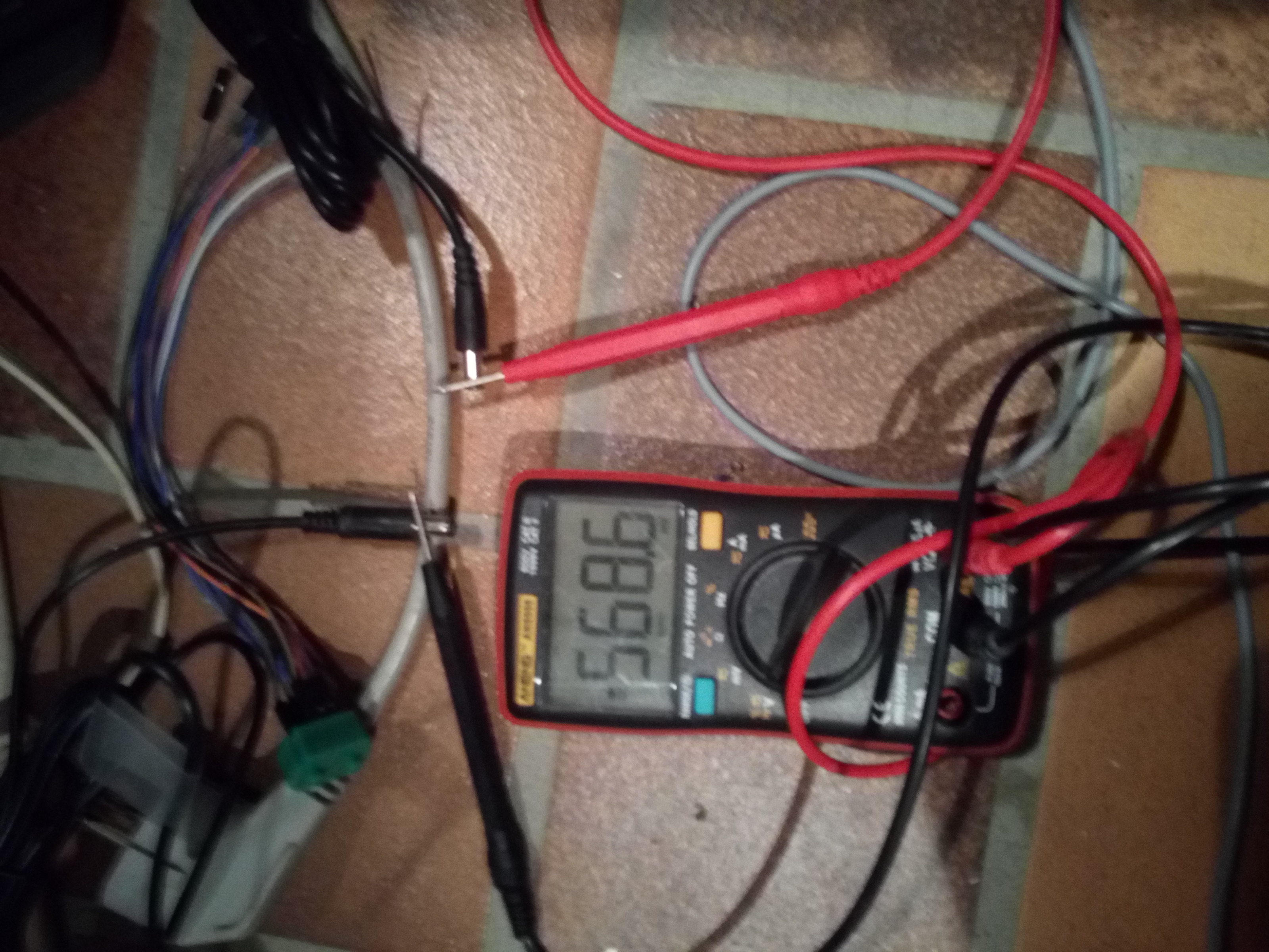
Siehe meine Messung (der maximale Potenzialunterschied den ich gesehen habe war 6V! Und das bei einem 12V und einem 5V Netzteil)
Replied by Louis Cypher on topic Mach3 5 Axis China BoB: 5 V Versorgung
Ich verstehe was Du meinst, den Satz könnte aber jemand missverstehen. Masse ist immer nur ein Bezugspunkt und eben nicht immer 0VBeispiel:
Masse ist Masse (0V). Und die sollte immer über alles gleich sein (verbunden).
Siehe meine Messung (der maximale Potenzialunterschied den ich gesehen habe war 6V! Und das bei einem 12V und einem 5V Netzteil)
Attachments:
Please Log in or Create an account to join the conversation.
- Mike_Eitel
-
- Offline
- Platinum Member
-
Less
More
- Posts: 1052
- Thank you received: 183
06 Oct 2019 18:17 #147280
by Mike_Eitel
Replied by Mike_Eitel on topic Mach3 5 Axis China BoB: 5 V Versorgung
I'm using a few hundred ohms or maybe 1k and yes as long as I see any voltage something is not OK. There should be no voltage and in fact I try mostly to avoid "high level floating charge".
The capacitor maybe 100n parallel with some small few nano ceramic. These are to shortcut the emv fx. of agressif high current stepper pulses etc. Also I use external stepper driver and sheelded cables with toroids...
Maybe a bit overdone for 24v sensorics and 75v steppers.. Plus all with superb 7i76e.
Please Log in or Create an account to join the conversation.
- Louis Cypher
- Offline
- Senior Member
-
Less
More
- Posts: 45
- Thank you received: 0
09 Oct 2019 20:22 #147595
by Louis Cypher
Replied by Louis Cypher on topic Mach3 5 Axis China BoB: 5 V Versorgung
Noch eine wahrscheinlich dumme Frage: Wo kann ich denn einen Widerstand in den Ground löten, wenn ich eine externe Stromversorgung habe statt USB? Wenn ich den in den Ground der Stromversorgung löte habe ich nur ein paar hundert Millivolt auf dem Board, weil natürlich nichts über die Groundverbindung geht, weil da der Widerstand drin ist. Der Ground zum PC ist ja gar nicht zugänglich.
Please Log in or Create an account to join the conversation.
- Mike_Eitel
-
- Offline
- Platinum Member
-
Less
More
- Posts: 1052
- Thank you received: 183
10 Oct 2019 06:42 #147614
by Mike_Eitel
Replied by Mike_Eitel on topic Mach3 5 Axis China BoB: 5 V Versorgung
Die Frage ist ob Deine Stromkreise galvanisch getrennt sind oder nicht. Nur wenn ja, dann besagte Ankopplung machen um hohe floating Potentiale zu vermeiden. Es geht darum Stromschleifen zwischen Masse und Erde zu vermeiden.
Please Log in or Create an account to join the conversation.
- spicer
-

- Offline
- Platinum Member
-
Less
More
- Posts: 422
- Thank you received: 126
10 Oct 2019 06:44 - 10 Oct 2019 06:45 #147615
by spicer
Replied by spicer on topic Mach3 5 Axis China BoB: 5 V Versorgung
Ich halt mich jetzt raus hier.
Aber ich sagte hier mal, dass Masse = Masse ist.
Was soll das Ganze.
Verschiedene Massen produzieren?
Normalerweise ist das genau das, was man vermeiden will!
Aber ich sagte hier mal, dass Masse = Masse ist.
Was soll das Ganze.
Verschiedene Massen produzieren?
Normalerweise ist das genau das, was man vermeiden will!
Last edit: 10 Oct 2019 06:45 by spicer.
Please Log in or Create an account to join the conversation.
Moderators: Muecke
Time to create page: 0.170 seconds