writing chip conveyor component , user input wanted
- tommylight
-

- Away
- Moderator
-

- Posts: 21271
- Thank you received: 7262
Back on topic, the idea was to use it as the normal two relay system, so just using forward and reverse on the connector you highlighted.
Please Log in or Create an account to join the conversation.
- chris@cnc
- Offline
- Platinum Member
-

- Posts: 529
- Thank you received: 140
Please Log in or Create an account to join the conversation.
- smc.collins
- Offline
- Platinum Member
-

- Posts: 717
- Thank you received: 138
are there any features I am missing ?
Couldn't tell from your explanation, but having an adjustable run on/off timer would be nice.
Maybe something like:
- Mode 1
- On with spindle on, off-delay when spindle off
- M100.1 FWD
- M100.2 REV
- OFF at M101 or M5
- Mode 2
- On-off repeating cycle while spindle on, off-delay when spindle off
- i.e. set to come on for X seconds every M2/M30 or 2 minutes or some other frequency
- Saves wear on the conveyor. I have small parts that don't need constant chip clearing, but still need periodic dumping
- M100.1 Px Qx (P-on time, Q-off time)
- Mode 3
- Manual FWD/REV/OFF override
- No M-code needed, just straight pushbutton activation.
- Useful if you're standing there and timing how long it takes to clear chips per cycle, or just need to clear some out while it's running a program
that's quiet the laundry list, not that I think it's terrible. the only time I've ever reversed my conveyor is when it jammed, Is there some use case where a M cdoe call for conveyor reverse makes sense ?
adding some manual switch inputs for mode 3 is easy. break down in a bit more detail how you'd want the conveyor to cycle ?
Please Log in or Create an account to join the conversation.
- smc.collins
- Offline
- Platinum Member
-

- Posts: 717
- Thank you received: 138
If someone wants to write the M code calls or set them up, I haven't really messed around with it much. I can expose hal pins, the variable speed thing is interesting, but how does someone implement that, m codes ? or a potentiometer interface like a feed override type signal ?chris@cnc post=294132 userid=25067Thanks, my thought was that it doesn't need a custom comp for a simple on/off chip conveyor. If someone is already making this effort, we could also talk about this solution. And based on my experience, I think that's very cool. Chips can be very annoying, and a chip conveyor that has an interval function or can regulate the speed is a good tool. And if the comp also provides additional outputs for one or two flushing pumps, almost everything has been thought of. This would also make it easy to use a custom interface to switch these things on or off individually. E.g. automatic, interval automatic, with or without flushing, or with M codes.
Please Log in or Create an account to join the conversation.
- spumco
- Offline
- Platinum Member
-

- Posts: 1974
- Thank you received: 808
Is there some use case where a M cdoe call for conveyor reverse makes sense ?
I can't honestly think of a case where you'd want to reverse using an M-code during a program. My brain was on autopilot and threw it in there.
HAAS uses M31-FWD and M33-STOP. Duty cycle are adjusted in a separate settings page.
Because a 'settings page' is so GUI-dependent in LCNC, I think using P- and Q-numbers would be more GUI-agnostic for LCNC. Nobody wants to fiddle with hal pin values before loading LCNC, and having to create a pair of data entry fields to integrate in to a GUI would be a pain.
So exposing hal pins for on-time and off-time would permit the end user to connect P/Q values to those pins. Or create a GUI data-entry field. Whichever way they want.
One each: on-pin time and off-pin time. Default the on-pin to 1, off-pin to 0. Calculate in minutes maybe.
So...
Mxx = 100% running while the program is active (or spindle running, your call)
Mxx P0.5 Q2 = 30 seconds on, minutes off
And no need for the Mxx.1 stuff I mentioned earlier.
If you want an example of a on/off component I found a while back, blink.comp has been extremely useful to me for simple on-off cycle stuff (LEDs, fans, pumps, etc.). It's so handy I think it should be added to the mainline comps.
Please Log in or Create an account to join the conversation.
- spumco
- Offline
- Platinum Member
-

- Posts: 1974
- Thank you received: 808
Please Log in or Create an account to join the conversation.
- smc.collins
- Offline
- Platinum Member
-

- Posts: 717
- Thank you received: 138
If you're brain is working better than mine right now, let work out the flow chart.
On another note, I'm working on a big integrated hal. component where all of my lathe specific comps will go. I was thining Lint.comp lathe integration component.
Please Log in or Create an account to join the conversation.
- spumco
- Offline
- Platinum Member
-

- Posts: 1974
- Thank you received: 808
If you're brain is working better than mine right now, let work out the flow chart.
That's a stretch. Mine hurts from CAD-Tetrising the sheetmetal around my lathe & stand.
But we can have a go at it. I use Libreoffice for flowcharts - ok with you or have you got a better idea for visualizign the sequencing and permissives?
Please Log in or Create an account to join the conversation.
- chris@cnc
- Offline
- Platinum Member
-

- Posts: 529
- Thank you received: 140
Standard selection could be:
Chip Conveyor start/stop with input pin in middle speed.(Maybe program run or M-Code)
Any other function select over panel.
I wrote a simple interval function for my mist collector. This function could break the out pin and we have interval. Attach example...
And for speed. 3 simple out pins to select speed input on VFD. I guess analog control is a little overkill. 3 speed mode should be okay in case of VFD using.
Please Log in or Create an account to join the conversation.
- chris@cnc
- Offline
- Platinum Member
-

- Posts: 529
- Thank you received: 140
I am not so good at making flow charts, but i could set up a simple on/off cycle. If you want, you can take a look. The comp is working.I think we should use the most common mcide for this conveyor on off cycle and mcodes are fin, i can just expose the hall pins for thise settings easily enough.
If you're brain is working better than mine right now, let work out the flow chart.
On another note, I'm working on a big integrated hal. component where all of my lathe specific comps will go. I was thining Lint.comp lathe integration component.
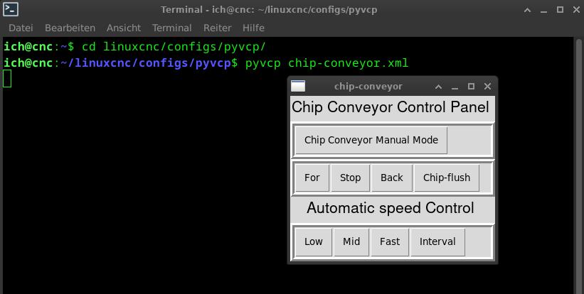
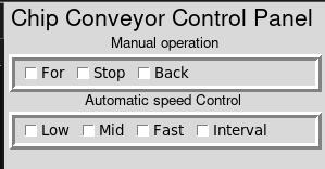
in0 starts the fwd pin. And if in7 high will be fwd pin cut by interval cycle time. Timer length could be set with hal setp.
in1 is manual fwd
in2 is stopp
in3 is manual back
chip flush is set if conveyor run.
The speed could also set up direct to VFD pins.
What do you think?
Please Log in or Create an account to join the conversation.


