Absolute linear scales
- terkaa
- Offline
- Elite Member
-

Less
More
- Posts: 261
- Thank you received: 3
21 Sep 2016 19:00 #80732
by terkaa
Replied by terkaa on topic Absolute linear scales
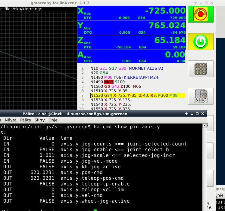
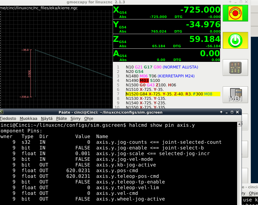
I have this position line in NC program
G54
G00 Y-35
It results in DRO reading -34.976mm and DTG shows 0.000 If I modify NC program:
G54
G00 Y-35.024
It results in DRO reading -35.000mm and DTG shows 0.000
I believe position shown in DRO is correct so problem is with commanded position.
Tero
G54
G00 Y-35
It results in DRO reading -34.976mm and DTG shows 0.000 If I modify NC program:
G54
G00 Y-35.024
It results in DRO reading -35.000mm and DTG shows 0.000
I believe position shown in DRO is correct so problem is with commanded position.
Tero
Please Log in or Create an account to join the conversation.
- andypugh
-

- Offline
- Moderator
-

Less
More
- Posts: 19797
- Thank you received: 4606
21 Sep 2016 19:02 #80733
by andypugh
Replied by andypugh on topic Absolute linear scales
The GUIs can be set to show absolute or commanded position.
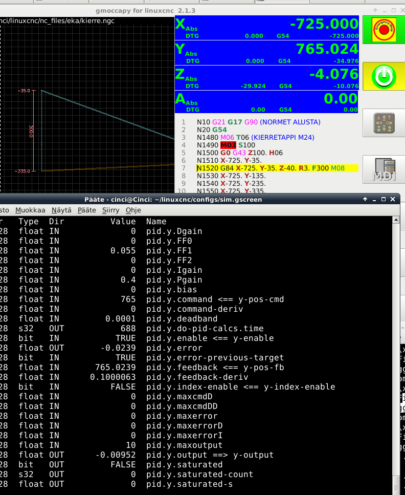
Also, have a look in Halshow (or with Halmeter) and see what the PID command, feedback, error and output are. (If I am right to think that this is a servo system)
Also, have a look in Halshow (or with Halmeter) and see what the PID command, feedback, error and output are. (If I am right to think that this is a servo system)
Please Log in or Create an account to join the conversation.
- terkaa
- Offline
- Elite Member
-

Less
More
- Posts: 261
- Thank you received: 3
22 Sep 2016 08:13 - 22 Sep 2016 08:46 #80765
by terkaa


Do these help? It seems that my error is in pid.y.error... Approaching direction does not have an affect. Do I understand correctly that control sees this -0.0239 postion error and tries to move Y by outputting -0.00952 volts to Servo Amp but it does not move with that voltage? Should I check if I have some setting in servo amp so that voltages below 0.01 are ignored? Or can this be solved by tuning PID?
Tero
Replied by terkaa on topic Absolute linear scales


Do these help? It seems that my error is in pid.y.error... Approaching direction does not have an affect. Do I understand correctly that control sees this -0.0239 postion error and tries to move Y by outputting -0.00952 volts to Servo Amp but it does not move with that voltage? Should I check if I have some setting in servo amp so that voltages below 0.01 are ignored? Or can this be solved by tuning PID?
Tero
Last edit: 22 Sep 2016 08:46 by terkaa.
Please Log in or Create an account to join the conversation.
- PCW
-

- Offline
- Moderator
-

Less
More
- Posts: 17687
- Thank you received: 5172
22 Sep 2016 13:51 #80768
by PCW
Replied by PCW on topic Absolute linear scales
Is .4 the highest P term you can use? (raising P would decrease the error in inverse proportion to the P value)
You could zero the 7I77 output/drive input offset by setting the PID bias to -0.00952V but down at this level, the 7I77s output and drives input drift will make this setting somewhat unstable
adding some I term will help also
You could zero the 7I77 output/drive input offset by setting the PID bias to -0.00952V but down at this level, the 7I77s output and drives input drift will make this setting somewhat unstable
adding some I term will help also
The following user(s) said Thank You: terkaa
Please Log in or Create an account to join the conversation.
- terkaa
- Offline
- Elite Member
-

Less
More
- Posts: 261
- Thank you received: 3
22 Sep 2016 15:56 #80776
by terkaa
Replied by terkaa on topic Absolute linear scales
0.5 started keeping noise. But I can try ie 0.45. I will also try adding a bit I to see what it does.
Tero
Tero
Please Log in or Create an account to join the conversation.
- PCW
-

- Offline
- Moderator
-

Less
More
- Posts: 17687
- Thank you received: 5172
22 Sep 2016 16:00 - 24 Sep 2016 15:16 #80777
by PCW
Replied by PCW on topic Absolute linear scales
I think the I value has to be fairly large before it makes much difference
(a small value will take a long time to respond)
(a small value will take a long time to respond)
Last edit: 24 Sep 2016 15:16 by PCW.
Please Log in or Create an account to join the conversation.
- andypugh
-

- Offline
- Moderator
-

Less
More
- Posts: 19797
- Thank you received: 4606
22 Sep 2016 20:44 #80813
by andypugh
Yes, exactly. With only a P-Gain term you can never actually get to the set point, it is a real-life example of Zeno's paradox Or maybe not exactly.
For some small error the output of a P-only controller will be too small to move the system. So you will always settle at that small error from the setpoint. (though it would normally be symmetrical for a horizontal axis)
That is why you need some I-term to integrate the small error over time until it becomes a big enough voltage to move that final little bit.
Add some Igain and you should see the error disappear Start with about P/10 and increase from there. Too much IGain will eventually give slow oscillations.
Replied by andypugh on topic Absolute linear scales
[Do these help? It seems that my error is in pid.y.error... Approaching direction does not have an affect. Do I understand correctly that control sees this -0.0239 postion error and tries to move Y by outputting -0.00952 volts to Servo Amp but it does not move with that voltage?
Yes, exactly. With only a P-Gain term you can never actually get to the set point, it is a real-life example of Zeno's paradox Or maybe not exactly.
For some small error the output of a P-only controller will be too small to move the system. So you will always settle at that small error from the setpoint. (though it would normally be symmetrical for a horizontal axis)
That is why you need some I-term to integrate the small error over time until it becomes a big enough voltage to move that final little bit.
Add some Igain and you should see the error disappear Start with about P/10 and increase from there. Too much IGain will eventually give slow oscillations.
The following user(s) said Thank You: terkaa
Please Log in or Create an account to join the conversation.
- terkaa
- Offline
- Elite Member
-

Less
More
- Posts: 261
- Thank you received: 3
22 Sep 2016 21:02 #80814
by terkaa
Replied by terkaa on topic Absolute linear scales
Ok, I tuning it is then. Btw this is HMC so Y in this case is vertical axis with hydraulic counterbalance.
Tero
Tero
Please Log in or Create an account to join the conversation.
- terkaa
- Offline
- Elite Member
-

Less
More
- Posts: 261
- Thank you received: 3
23 Sep 2016 06:44 #80821
by terkaa
Replied by terkaa on topic Absolute linear scales
Ok I was able to increase P to 0.48 and also adding 0.06 to I And now positioning accuracy is within +-0.0002 mm and that is good enough for me.
Tero
Tero
Please Log in or Create an account to join the conversation.
- terkaa
- Offline
- Elite Member
-

Less
More
- Posts: 261
- Thank you received: 3
03 Nov 2016 18:19 #82386
by terkaa
Replied by terkaa on topic Absolute linear scales
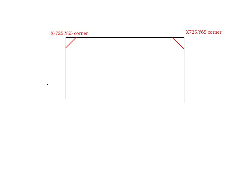
Today we noticed control cutting corners a lot with G00 moves. We have following G-code:
(current pos X-725. Y-100.)
G00 Y 65.
G00 X 725.
G00 Y -100.
In the first end about 40mm before reaching Y65. X starts to move towards 725. In the other end about 40mm before reaching X725. Y starts to move towards -100. Any ideas why? Attached is drawing of path. Black is what it should be and red is actual:
Tero
Please Log in or Create an account to join the conversation.
Time to create page: 0.113 seconds

