Sticking Home/Limit Switches - Please help
- McAdam
- Offline
- Junior Member
-

Less
More
- Posts: 32
- Thank you received: 0
01 Jun 2017 14:17 #93938
by McAdam
When machine is not enabled 9.0v & 8.1v
When Machine is enabled 9.6v & 7.6v
When Switch is Triggered 8.6v & 9.6v
When Stuck is same as when machine is enbabled
Replied by McAdam on topic Sticking Home/Limit Switches - Please help
So, the voltages at the screw terminals behave correctly, but the values on the parallel port pins don't.
How curious.
You could try measuring the voltages on each side of the opto-couplers (input and output pairs)
When machine is not enabled 9.0v & 8.1v
When Machine is enabled 9.6v & 7.6v
When Switch is Triggered 8.6v & 9.6v
When Stuck is same as when machine is enbabled
Please Log in or Create an account to join the conversation.
- McAdam
- Offline
- Junior Member
-
Less
More
- Posts: 32
- Thank you received: 0
01 Jun 2017 14:19 #93939
by McAdam
It is a good quality (Lindy) Straight through DB25 Cable. If it was not pinned to pin would I also have some other issues?
I can try and see If I can get another one from amazon, but I am fairly certain this one is good
Replied by McAdam on topic Sticking Home/Limit Switches - Please help
I am away for a few days. But I take it you are using a correct type of PP cable as they are not always pin to pin. Try another one.
It is a good quality (Lindy) Straight through DB25 Cable. If it was not pinned to pin would I also have some other issues?
I can try and see If I can get another one from amazon, but I am fairly certain this one is good
Please Log in or Create an account to join the conversation.
- tommylight
-

- Away
- Moderator
-

Less
More
- Posts: 21738
- Thank you received: 7428
01 Jun 2017 15:02 #93946
by tommylight
Replied by tommylight on topic Sticking Home/Limit Switches - Please help
That is a 5V BOB, so nowhere shout it have 9V.
Remove the step down converter from 12V to 5V, that might be the problem ( i can bet my pinky it is), some do the switching on the negative side so having both grounds together makes some trouble,
Get a USB cable, insert it on the motherboard and to the BOB, remove the step down converter, all should be good, although the optos might have gone the way of the DODO!
Please Log in or Create an account to join the conversation.
- McAdam
- Offline
- Junior Member
-
Less
More
- Posts: 32
- Thank you received: 0
01 Jun 2017 15:09 #93947
by McAdam
I have tried without the Step Down Converter and just USB cable, same thing happens.
Anyway to test/diagnose the optoisolators?
Replied by McAdam on topic Sticking Home/Limit Switches - Please help
That is a 5V BOB, so nowhere shout it have 9V.
Remove the step down converter from 12V to 5V, that might be the problem ( i can bet my pinky it is), some do the switching on the negative side so having both grounds together makes some trouble,
Get a USB cable, insert it on the motherboard and to the BOB, remove the step down converter, all should be good, although the optos might have gone the way of the DODO!
I have tried without the Step Down Converter and just USB cable, same thing happens.
Anyway to test/diagnose the optoisolators?
Please Log in or Create an account to join the conversation.
- tommylight
-
- Away
- Moderator
-
Less
More
- Posts: 21738
- Thank you received: 7428
01 Jun 2017 15:18 #93948
by tommylight
Replied by tommylight on topic Sticking Home/Limit Switches - Please help
I do not think it would be the same as you would at least have 5V on the inputs instead of 9V you are getting now.
In any case, remove the converter, almost all of the cheap ones do switching on the negative side, so they can not have - or gnd attached to any other source. I have plenty of them, all do switching on negative side.
Use USB cable. To test the optos, just measure the voltage on their outputs while closing the corresponding limit switch. Just check to see if they have common ground or common +, so attach one of the terminals to the gnd or +5V and the other terminal carefully to the output of the opto coupler.
Please Log in or Create an account to join the conversation.
- Todd Zuercher
-

- Away
- Platinum Member
-

Less
More
- Posts: 4761
- Thank you received: 1462
01 Jun 2017 15:42 #93951
by Todd Zuercher
Replied by Todd Zuercher on topic Sticking Home/Limit Switches - Please help
Tommy I think you may be wrong. I'm pretty sure the input side of the input optos are powered from the 12-24v.
It seems to me like when you have more than a couple of the inputs active the voltage there is dropping below a critical level for them.
Would it be too much trouble for you to test the board with more than a 12v supply (closer to the 24v). (It might be that an additional external pull-up might be nessisary when using the minimal 12v supply.)
Please Log in or Create an account to join the conversation.
- McAdam
- Offline
- Junior Member
-
Less
More
- Posts: 32
- Thank you received: 0
01 Jun 2017 15:53 #93954
by McAdam
Hmm.... I dont have anything higher, I guess I could just order something with Amazon.
OR Crazy thought,
I could test with the 18V battery from my drill.... Hmmmmm.... Ghetto/Macgyver Engineering
Replied by McAdam on topic Sticking Home/Limit Switches - Please help
It seems to me like when you have more than a couple of the inputs active the voltage there is dropping below a critical level for them.
Would it be too much trouble for you to test the board with more than a 12v supply (closer to the 24v). (It might be that an additional external pull-up might be nessisary when using the minimal 12v supply.)
Hmm.... I dont have anything higher, I guess I could just order something with Amazon.
OR Crazy thought,
I could test with the 18V battery from my drill.... Hmmmmm.... Ghetto/Macgyver Engineering
Please Log in or Create an account to join the conversation.
- tommylight
-
- Away
- Moderator
-
Less
More
- Posts: 21738
- Thank you received: 7428
01 Jun 2017 15:54 #93955
by tommylight
Replied by tommylight on topic Sticking Home/Limit Switches - Please help
Had 2 of them, they have finicky inputs and highly sensitive to interference, so i added some more pull up resistors and they are still working on plasma cutters, but i can not recall in any way or form it mentioned anything other than 5V anywhere, except on the relay output.
Then again, reading through a Chinese manual is like .......add your own comment here......") .
.
Comes to think of it, they do have a jumper for choosing the USB or terminal power. Did you check that?
Then again, reading through a Chinese manual is like .......add your own comment here......
.Comes to think of it, they do have a jumper for choosing the USB or terminal power. Did you check that?
Please Log in or Create an account to join the conversation.
- tommylight
-
- Away
- Moderator
-
Less
More
- Posts: 21738
- Thank you received: 7428
01 Jun 2017 15:57 - 01 Jun 2017 16:06 #93956
by tommylight
Aaaaand lots of smoke if something goes wrong !!! Those batteries can release quite some power in an instance!
Use a resistor of anything from 1 to 10 ohm in series with the battery. More=safer.
Found it ! It has 12-24V input but for 0-10V PWM output only ! I used them for plasma so i did not bother with that. Everything else on the board is 5V.
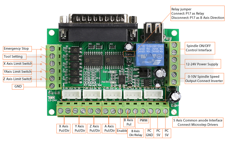
Those are 74HC245, Absolute maximum 7V, normal operating voltage 5.5V max.
Replied by tommylight on topic Sticking Home/Limit Switches - Please help
OR Crazy thought,
I could test with the 18V battery from my drill.... Hmmmmm.... Ghetto/Macgyver Engineering
Aaaaand lots of smoke if something goes wrong !!!
Those batteries can release quite some power in an instance!Use a resistor of anything from 1 to 10 ohm in series with the battery. More=safer.
Found it ! It has 12-24V input but for 0-10V PWM output only ! I used them for plasma so i did not bother with that. Everything else on the board is 5V.
Those are 74HC245, Absolute maximum 7V, normal operating voltage 5.5V max.
Last edit: 01 Jun 2017 16:06 by tommylight.
Please Log in or Create an account to join the conversation.
- McAdam
- Offline
- Junior Member
-
Less
More
- Posts: 32
- Thank you received: 0
01 Jun 2017 16:04 #93958
by McAdam
I think we might have slightly different boards.
The only jumper on this one is to switch PIN 1 between relay and B AXIS pins.
Without 12v+ the inputs are dead.
Replied by McAdam on topic Sticking Home/Limit Switches - Please help
Had 2 of them, they have finicky inputs and highly sensitive to interference, so i added some more pull up resistors and they are still working on plasma cutters, but i can not recall in any way or form it mentioned anything other than 5V anywhere, except on the relay output.
Then again, reading through a Chinese manual is like .......add your own comment here......
Comes to think of it, they do have a jumper for choosing the USB or terminal power. Did you check that?
I think we might have slightly different boards.
The only jumper on this one is to switch PIN 1 between relay and B AXIS pins.
Without 12v+ the inputs are dead.
Please Log in or Create an account to join the conversation.
Time to create page: 1.422 seconds