Homing sensors issue with parallel port BOB
- Muz94
- Offline
- Senior Member
-

Less
More
- Posts: 79
- Thank you received: 2
13 Mar 2018 20:37 - 13 Mar 2018 20:42 #107297
by Muz94
Homing sensors issue with parallel port BOB was created by Muz94
Hi everyone.
I'm wiring the control box of my 3d printer, and i need to connect the 6 limit switches / homing sensors to a common pin of the BOB.
The BOB is this one:
warp9td.com/images/BOB_Vendors/StepperOnline/ST-V2.pdf
As stated in the pdf the input pins of that board are 12-24 volt tolerant, so i connected the output of my sensors (connected in series to each other) to the GND / P13 pins.
The problem is that the value read from Linuxcnc for that pin is always TRUE (or false if I invert it).
Do you have any idea of how to set up this kind of configuration?
This is my hal setup:
net XYZ-lim parport.0.pin-13-in-not => axis.0.pos-lim-sw-in
net XYZ-lim parport.0.pin-13-in-not => axis.1.pos-lim-sw-in
net XYZ-lim parport.0.pin-13-in-not => axis.2.pos-lim-sw-in
net XYZ-lim parport.0.pin-13-in-not => axis.0.neg-lim-sw-in
net XYZ-lim parport.0.pin-13-in-not => axis.1.neg-lim-sw-in
net XYZ-lim parport.0.pin-13-in-not => axis.2.neg-lim-sw-in
net XYZ-lim parport.0.pin-13-in-not => axis.0.home-sw-in
net XYZ-lim parport.0.pin-13-in-not => axis.1.home-sw-in
net XYZ-lim parport.0.pin-13-in-not => axis.2.home-sw-in
Thank you very much
Last edit: 13 Mar 2018 20:42 by Muz94.
Please Log in or Create an account to join the conversation.
- DanMN
-

- Offline
- Senior Member
-
Less
More
- Posts: 74
- Thank you received: 10
13 Mar 2018 21:30 #107298
by DanMN
Replied by DanMN on topic Homing sensors issue with parallel port BOB
Do you know if you have PNP or NPN sensors? Is there any guidance on what type of input the ST-V2 expects? I started with that BOB, but gave up after hitting limits in my design and the very minimal documentation for things like that, so you might have to hunt for an answer. In my case, I had NPN sensors and had to use pullup resistors on the inputs to get a the controller to recognize high/low differential.
Please Log in or Create an account to join the conversation.
- raglanlittlejohn
- Offline
- Senior Member
-
Less
More
- Posts: 76
- Thank you received: 9
13 Mar 2018 21:30 #107299
by raglanlittlejohn
Replied by raglanlittlejohn on topic Homing sensors issue with parallel port BOB
I think you just need something like,
net XYZ-lim parport.0.pin-13-in-not => axis.0.pos-lim-sw-in => axis.1.pos-lim-sw-in => axis.2.pos-lim-sw-in
The signal can have lots of destinations, but only one source.
You need power on the 12-24V Power Supply. Is pin 13 being pulled down to GND / released at limits, by the sensors.
net XYZ-lim parport.0.pin-13-in-not => axis.0.pos-lim-sw-in => axis.1.pos-lim-sw-in => axis.2.pos-lim-sw-in
The signal can have lots of destinations, but only one source.
You need power on the 12-24V Power Supply. Is pin 13 being pulled down to GND / released at limits, by the sensors.
Please Log in or Create an account to join the conversation.
- Muz94
- Offline
- Senior Member
-
Less
More
- Posts: 79
- Thank you received: 2
13 Mar 2018 21:38 #107301
by Muz94
Replied by Muz94 on topic Homing sensors issue with parallel port BOB
I'm using PNP NC sensors, that i connected as in attachment.
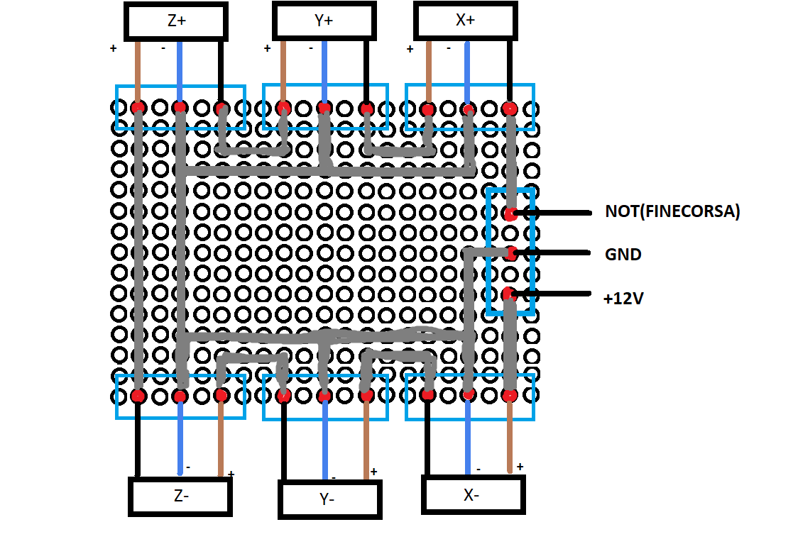
That way when i put something close to one of the sensors, all the following ones get disconnected and i get 0v between the black and the blue wire. Is it correct? It looks correct by looking at the lights shutting down behind the sensors...
@raglanlittlejohn I just discovered that i have to connect those 2 pins form the comment section of a youtube video....
The problem is that with those 2 pins connected to the power supply, and the final black wire of the sensors chain connected to pin 13, the light on the sensors won't shut down completely when i put an object in front of them (they just dim, and that makes me think that i'm doing something completely wrong).
Please Log in or Create an account to join the conversation.
- Muz94
- Offline
- Senior Member
-
Less
More
- Posts: 79
- Thank you received: 2
13 Mar 2018 21:46 #107303
by Muz94
Replied by Muz94 on topic Homing sensors issue with parallel port BOB
thinking at how a pnp nc sensor works, i'm starting to think that i need a pulldown resistor
Please Log in or Create an account to join the conversation.
- andypugh
-

- Offline
- Moderator
-

Less
More
- Posts: 19886
- Thank you received: 4645
13 Mar 2018 22:25 #107308
by andypugh
Replied by andypugh on topic Homing sensors issue with parallel port BOB
Your diagram shows output wires (black) connecting to Power inputs of some sensors.
I am not sure that's a good way to do it.
I think you can connect all the outputs to one point, and that point will get pulled-up to supply voltage if any one sensor is triggered (would be pulled down to GND if they were NPN).
Maybe test it with two loose sensors to see if I am correct (I only have NPN ones here)
Please Log in or Create an account to join the conversation.
- andypugh
-
- Offline
- Moderator
-
Less
More
- Posts: 19886
- Thank you received: 4645
13 Mar 2018 22:28 #107309
by andypugh
Replied by andypugh on topic Homing sensors issue with parallel port BOB
See the "DC 3-Wire OR" configuration at the bottom of this page:
www.omron-ap.com/service_support/FAQ/FAQ00311/index.asp
www.omron-ap.com/service_support/FAQ/FAQ00311/index.asp
Please Log in or Create an account to join the conversation.
- Muz94
- Offline
- Senior Member
-
Less
More
- Posts: 79
- Thank you received: 2
14 Mar 2018 00:23 #107320
by Muz94
Replied by Muz94 on topic Homing sensors issue with parallel port BOB
It doesn't seem to work that way.
However my sensors are pnp nc, they should be putting out supply voltage until they trigger, shouldn't they?
I tryed with 1 signle sensor and that way it works (however i get en error if i try to "simulate" the homing process by hand, but that's not the main issue now).
However my sensors are pnp nc, they should be putting out supply voltage until they trigger, shouldn't they?
I tryed with 1 signle sensor and that way it works (however i get en error if i try to "simulate" the homing process by hand, but that's not the main issue now).
Please Log in or Create an account to join the conversation.
- andypugh
-
- Offline
- Moderator
-
Less
More
- Posts: 19886
- Thank you received: 4645
14 Mar 2018 00:27 #107322
by andypugh
Replied by andypugh on topic Homing sensors issue with parallel port BOB
PNP NC is a bit awkward.
Though with holes for targets rather than bumps it would still work.
My machines all tend to have holes for targets so that sensor failure is safer (It is also often quite a lot easier when you are burying the proxes inside the machine slides)
Though with holes for targets rather than bumps it would still work.
My machines all tend to have holes for targets so that sensor failure is safer (It is also often quite a lot easier when you are burying the proxes inside the machine slides)
Please Log in or Create an account to join the conversation.
- Muz94
- Offline
- Senior Member
-
Less
More
- Posts: 79
- Thank you received: 2
14 Mar 2018 00:37 #107323
by Muz94
Replied by Muz94 on topic Homing sensors issue with parallel port BOB
mmm
i'll do more experiments tomorrow (now it's 1.40AM here).
Thank you for your help!
i'll do more experiments tomorrow (now it's 1.40AM here).
Thank you for your help!
Please Log in or Create an account to join the conversation.
Time to create page: 0.110 seconds