Homing sensors issue with parallel port BOB
- Muz94
- Offline
- Senior Member
-

Less
More
- Posts: 79
- Thank you received: 2
14 Mar 2018 09:39 - 14 Mar 2018 09:40 #107336
by Muz94
Replied by Muz94 on topic Homing sensors issue with parallel port BOB
Update:
the circuit of the first picture actually works, the problem is that when the final black wire is connected to pin 13 the leds behind the sensors dim instead of turning off completely, like if there is some current back feeding from the board to the sensors, but i can see a value change ti the pin value in the HAL Meter..
As a complete "electronic noob" i was thinking about putting a diode to avoid that. Does it make any sense?
Last edit: 14 Mar 2018 09:40 by Muz94.
Please Log in or Create an account to join the conversation.
- Muz94
- Offline
- Senior Member
-
Less
More
- Posts: 79
- Thank you received: 2
14 Mar 2018 16:53 - 14 Mar 2018 17:15 #107353
by Muz94
Replied by Muz94 on topic Homing sensors issue with parallel port BOB
Do you have any idea of where i could find a scheme for tat BOB?
I'm trying to understand what is going on by looking at how the various components are connected, but i'm quite lost.
I see that the bottom left pin of the optocouplers (that should be the cathode of the built in LED) is connected via a 1kOhm resistor to the input pins, and i can clearly measure a 2,3kOhm resistance between the top pin (that should be the anode) and GND, and this is exactly the opposite of what i was expecting...
edit:
For example i have a small board with 4 oprocouplers, and those are connected in a more common way.
The 2 input pins go directly into the 2 left pins of the optocpupler (with a 2,2kOhm resistor to protect a small led that shows the logic value of the input), while the 2 right pins are simply connected to ground (the bottom one) and to vcc with a 10kOhm pullup resistor (the top one).
Last edit: 14 Mar 2018 17:15 by Muz94.
Please Log in or Create an account to join the conversation.
- Muz94
- Offline
- Senior Member
-
Less
More
- Posts: 79
- Thank you received: 2
15 Mar 2018 19:28 - 15 Mar 2018 19:51 #107390
by Muz94
Replied by Muz94 on topic Homing sensors issue with parallel port BOB
After googling a lot searching for schematics of similar BOBs, PNP NC sensors ecc i came up with this that I THINK should be an approximation of what is going on:
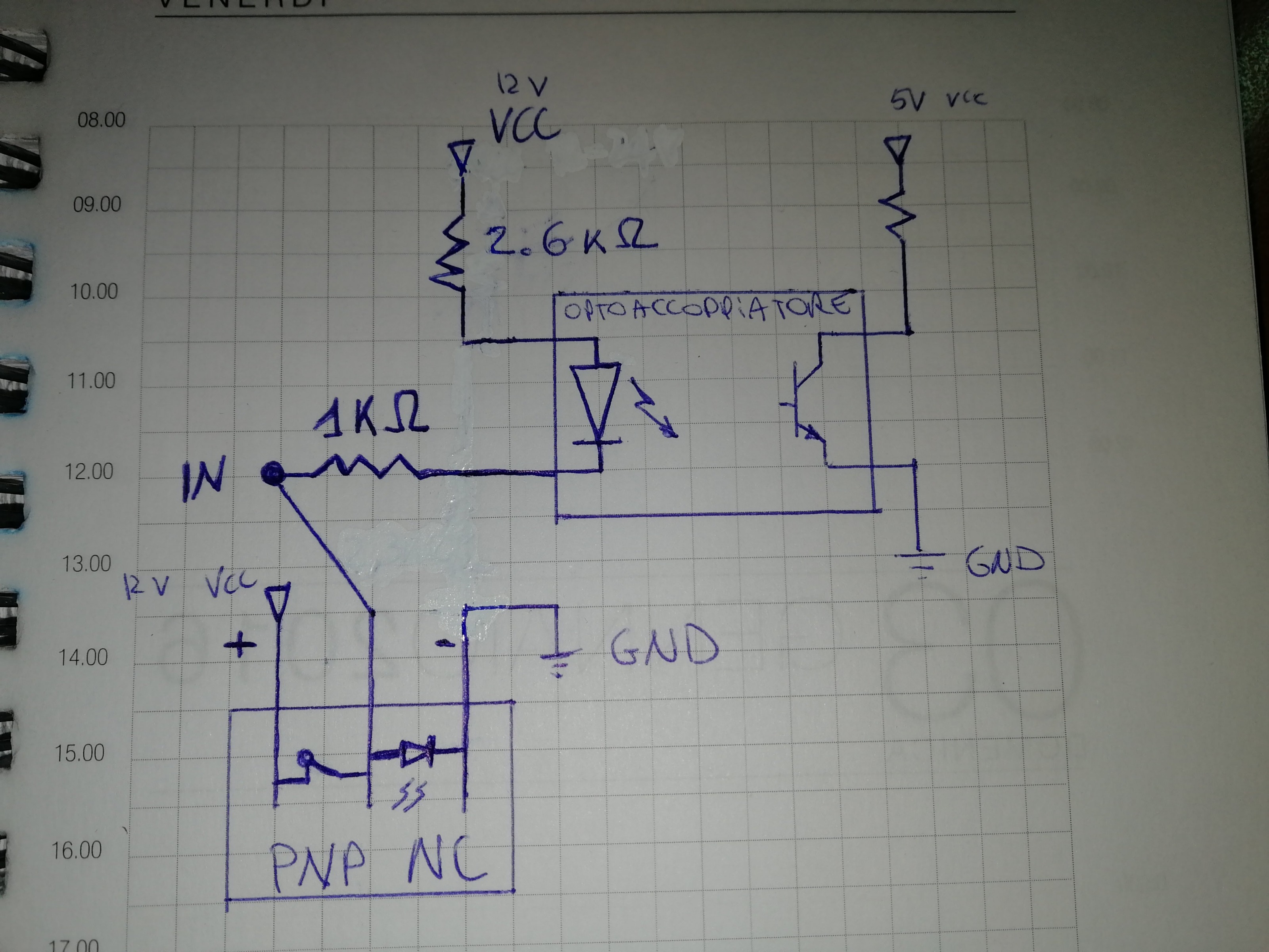
What i understood is that this kind of BOB is just made to have inputs like E-STOPS, mechanic switches ecc, because it simply wants the inputs to be driven by connecting / disconnecting them to /from gnd.
I assumed the position of the led into the sensors: that should explain why the leds only dim: the current from vcc, once the switch gets opened (when the sensor has something near) , can flow to gnd passing through the leds.
Also this would mean that actually those sensors only work thanks to the path to ground that is created through those LEDS...
Does this make sense?
How can i fix this? It looks that i simply have a BOB that is not meant to be used with this kind of sensor..
Last edit: 15 Mar 2018 19:51 by Muz94.
Please Log in or Create an account to join the conversation.
- andypugh
-

- Away
- Moderator
-

Less
More
- Posts: 19863
- Thank you received: 4636
15 Mar 2018 20:17 #107393
by andypugh
Were the sensors expensive? NPN would simplify things.
Replied by andypugh on topic Homing sensors issue with parallel port BOB
How can i fix this? It looks that i simply have a BOB that is not meant to be used with this kind of sensor..
Were the sensors expensive? NPN would simplify things.
Please Log in or Create an account to join the conversation.
- Muz94
- Offline
- Senior Member
-
Less
More
- Posts: 79
- Thank you received: 2
15 Mar 2018 20:28 - 15 Mar 2018 20:39 #107394
by Muz94
Replied by Muz94 on topic Homing sensors issue with parallel port BOB
No, not really.
6 sensors for 2-3 euros each.
I will consider buying some NPN then.
Should i stick with NC? I bought them because i felt they were safer, but in this configuration even if i detach one of them, it doesn't trigger a limit error in linuxcnc.
With NPN however it should be different if i'm correct, the path to ground would be normally closed, and detaching one sensor would definitely change the logic value read by the control.
edit: i'm not fully sure that i really understood how everything works however, if the circuit is the one i drew i still don't understand how the bob is picking the correct logic level of the sensor... the path to ground should always be closed, but i guess that i don't really have enough knowledge of how all the pull-up / pull-down thing works
Last edit: 15 Mar 2018 20:39 by Muz94.
Please Log in or Create an account to join the conversation.
- andypugh
-
- Away
- Moderator
-
Less
More
- Posts: 19863
- Thank you received: 4636
15 Mar 2018 20:50 #107398
by andypugh
Replied by andypugh on topic Homing sensors issue with parallel port BOB
I think that I would suggest choosing NC or NO based on each particular target.
I think I would wire them all to a common point, with them all open in their normal position (either detecting a target or detecting a hole). Then I think that any one of them can switch the input pin to GND.
I think I would wire them all to a common point, with them all open in their normal position (either detecting a target or detecting a hole). Then I think that any one of them can switch the input pin to GND.
Please Log in or Create an account to join the conversation.
Time to create page: 0.103 seconds