What Do I Need for ESTOP and Safety Circuitry?
- Lethal69GTO
-
 Topic Author
- Offline
- Junior Member
-

- Posts: 29
- Thank you received: 4
- "Axis" 3-axis configuration, X, Y1, Y2, Z.
- Mesa 7i76E.
- 120VAC 2.2kW water-cooled spindle (Z-mounted, but not connected to VFD).
- Huanyang VFD (powers up).
- PNP proximity sensors at both ends of X, Y1, and Y2. Z only has software limits defined.
- Prox sensors wired to 3-wire PLC input module, 6-way sensor terminal block with the signals wired to Mesa digital-in. HAL "sees" the states of the prox sensors which appropriately change when triggered. Home and min/max limits have not been defined - yet. That is for another day. At the moment only software limits defined for all axis.
- Main multi-branch power circuit enters emergency "oh sh*t" paddle switch mounted to the enclosure, much like a table saw or router table. Pushing the paddle terminates power to the entire enclosure, everything turns off - motion and control.
- From paddle switch, multi-branch main power circuit enters enclosure to door mounted two-position lock-out type main power rotary switch. One branch is power for typical 2-button 120VAC 24VDC coil contactor holding circuit, attached to it is all motion (VFD and D542 drivers). Power to motion side can be killed entirely as expected with the holding circuit being turned "off". The other phase provides power to the control side (Mesa, exhaust fan, and other peripheries). The control side power is turned off when the main power rotary switch is turned off.
- Connect a Mesa TB1 field power output (pin 0-3) to the NO in terminal of the e-stop button. Using more than one e-stop button requires wiring the NO circuitry in parallel so that a possible malfunctioning switch along the chain does not cause an unwanted e-stop signal - the switch must be intentionally depressed by human action.
- Connect the e-stop NO out terminal to Mesa digital-in pin (TB5 or TB6, pin number to determined for coding in HAL). This is the e-stop pressed "event notification" signal. In my case it is 24VDC.
- Connect Mesa digital-out (TB5 or TB6, pin number to be determined for coding in HAL) to +VDC terminal of solid-state relay.
Q: This and the GND connection will cause the relay to energize its coil and open (if NC relay) thereby removing the +5V signal from Mesa to the stepper drivers ENA+, thereby "disabling" them so they no longer output Step/Dir pulses to the stepper motors? Is that its intent?
Q: Does not removing power to ENA+ cause the stepper motors to stop moving? Power to them can be left on?
Q: Do I need a SPDT or DPDT and what kind NO only, NO/NC, NC only? I ordered two of these based on Rod's recommendation in one of the aforementioned threads, is this correct? Ultrathin DIN Rail Relay Module, MRD-060D2, Input 4-32VDC NO - Connect Mesa GND to -VDC terminal of solid-state relay.I think I am a-OK to this point. My conundrum is the "load" side of the relay. Stepper drivers ENA+ can accept +5V~24V and they and accompanying ENA- are NOT connected on my machine.
Q: Does that signal pulse have to come from the +5V terminal of one of the unused Mesa Step/Dir output connectors on TB2 or TB3? Does this Step/Dir output need to be added to the system configuration if I did not select 5 steppers in configuration wizard? It isn't being used as step/dir controller, how does the +5V terminal actually go high?
Q: Could the signal instead come from one of the Mesa digital-out terminals of TB5 or TB6 with a buck/step-down converter reducing the 24VDC to 10VDC max and programmed in HAL appropriately? Only need an "on" signal, right? I suppose the buck converter is another point of possible hardware failure to contend with. - Connect Mesa GND to D542 ENA- terminal.
Q: Does it actually matter the source of the Mesa ground? Could it be a "field ground" (terminal block connected to Mesa TB1 or to TB3 supply power ground) or does it have to also come from the same unused/spare Step/Dir output connector supplying the +5V? - Daisy-chain connect each of the D542 stepper driver's +ENA and -ENA.
Thank you.
Darryl
Please Log in or Create an account to join the conversation.
- PCW
-

- Offline
- Moderator
-

- Posts: 17917
- Thank you received: 5246
You should not switch the field powerConnect a Mesa TB1 field power output (pin 0-3) to the NO in terminal of the e-stop button. Using more than one e-stop button requires wiring the NO circuitry in parallel so that a possible malfunctioning switch along the chain does not cause an unwanted e-stop signal - the switch must be intentionally depressed by human action.
An ESTOP circuit should remove _primary_ power from the axis and spindle
Please Log in or Create an account to join the conversation.
- rodw
-

- Offline
- Platinum Member
-

- Posts: 11948
- Thank you received: 4068
There is a component called estop-latch which can be used to build the estop chain in software by using multiple instances of it. Its not well documented but works well but its probably not compliant in a commercial sense. But it worked fine for me.
This video explains this in more detail.
forum.linuxcnc.org/24-hal-components/379...w-things-work-series
In a commercial setting, you should be using a standards compliant safety switch. They add a lot of complexity to the circuitry as each component in the circuit has dual redundancy.
Please Log in or Create an account to join the conversation.
- Aciera
-

- Offline
- Administrator
-

- Posts: 4707
- Thank you received: 2106
Note that some VFDs/motor drivers offer a dedicated safety input that will bring the motor to a controlled stop within a defined time rather than just having it run out when mains power is cut. This is the usual requirement in an industrial setting these days.
What level of safety you need is up to you.
Please Log in or Create an account to join the conversation.
- rodw
-
- Offline
- Platinum Member
-
- Posts: 11948
- Thank you received: 4068
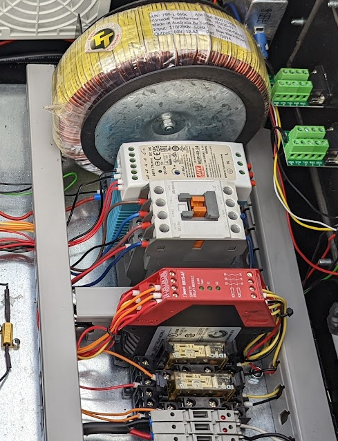
In terms of compliance with the relevant standards (which I am too lazy to look up), it not just enough to use a safety relay. I bought the red one shown here. Then I needed a couple of special force guided relays shown in front to trigger the contactor behind it. These have a non-conductive probe that is forced between the relay contacts to ensure they open if they are welded shut.Note that some VFDs/motor drivers offer a dedicated safety input that will bring the motor to a controlled stop within a defined time rather than just having it run out when mains power is cut. This is the usual requirement in an industrial setting these days.
But this circuit simply drops power to the drives and spindle which is not desirable. What I should have done is to use a timer relay so the spindle and drives could be disabled gracefully before the circuits were turned off. But for compliance, I could not use an ordinary (non-standards compliant) timer relay so I should have used a safety relay with a timer built in to preserve the safety circuit. All of this adds a lot to cost so for home use where an employee is not using the machine, simple is good!
Please Log in or Create an account to join the conversation.
- rodw
-
- Offline
- Platinum Member
-
- Posts: 11948
- Thank you received: 4068
Attachments:
Please Log in or Create an account to join the conversation.
- Lethal69GTO
-
Topic Author
- Offline
- Junior Member
-
- Posts: 29
- Thank you received: 4
Thank you for all responding. Ultimately Aciera statement is my viewpoint. I was seeking input from the experts and those in know with the wiring and hardware but I see there is conflicting opinion with respect cutting main power to drivers and motors or not to and the definition of what an e-stop is and underlying control function.What level of safety you need is up to you.
I am sure this topic has been discussed many times over and I do not profess to be an industrial control expert and would rather not open the Pandora's Box. The state of the machine all depends on the level of stop category one desires, from what I have found:
- Level 0 is an uncontrolled stop immediately removing power to the machine actuators.
- Level 1 is a controlled stop with power available to the machine actuators to achieve the stop and then removal of power when the stop is achieved.
- Level 2 is a controlled stop with power left available to the machine actuators.
Again, appreciate the input from all.
- Darryl
Please Log in or Create an account to join the conversation.
- D.L.
- Offline
- Senior Member
-

- Posts: 55
- Thank you received: 37
Attachments:
Please Log in or Create an account to join the conversation.